
Split joint type decorated sheet

A decorative board and splicing technology, which is applied in the direction of sheet/board, furniture connection, connection components, etc., can solve the problems of poor overall aesthetics and mutual versatility, damage to decorative items, unreasonable positioning, etc., and achieves simple structure, Not easy to fall off, easy to splicing and installation

Inactive Publication Date: 2008-08-06
李新发
View PDF1 Cites 13 Cited by
  • Summary
  • Abstract
  • Description
  • Claims
  • Application Information

AI Technical Summary

Problems solved by technology

This kind of decoration is easy to cause damage to the decorative items, and the overall aesthetics and mutual versatility are poor
In order to solve the above problems, the applicant once applied to the China Patent Office on November 2, 2006 for an invention patent named "Combined Decorative Strip", the patent number is 200610124914.4. Although this patent solves the above problems, due to The positioning is unreasonable, and there is a defect that it is easy to fall off

Method used


Image

  • Split joint type decorated sheet
  • Split joint type decorated sheet

Examples


Embodiment 1

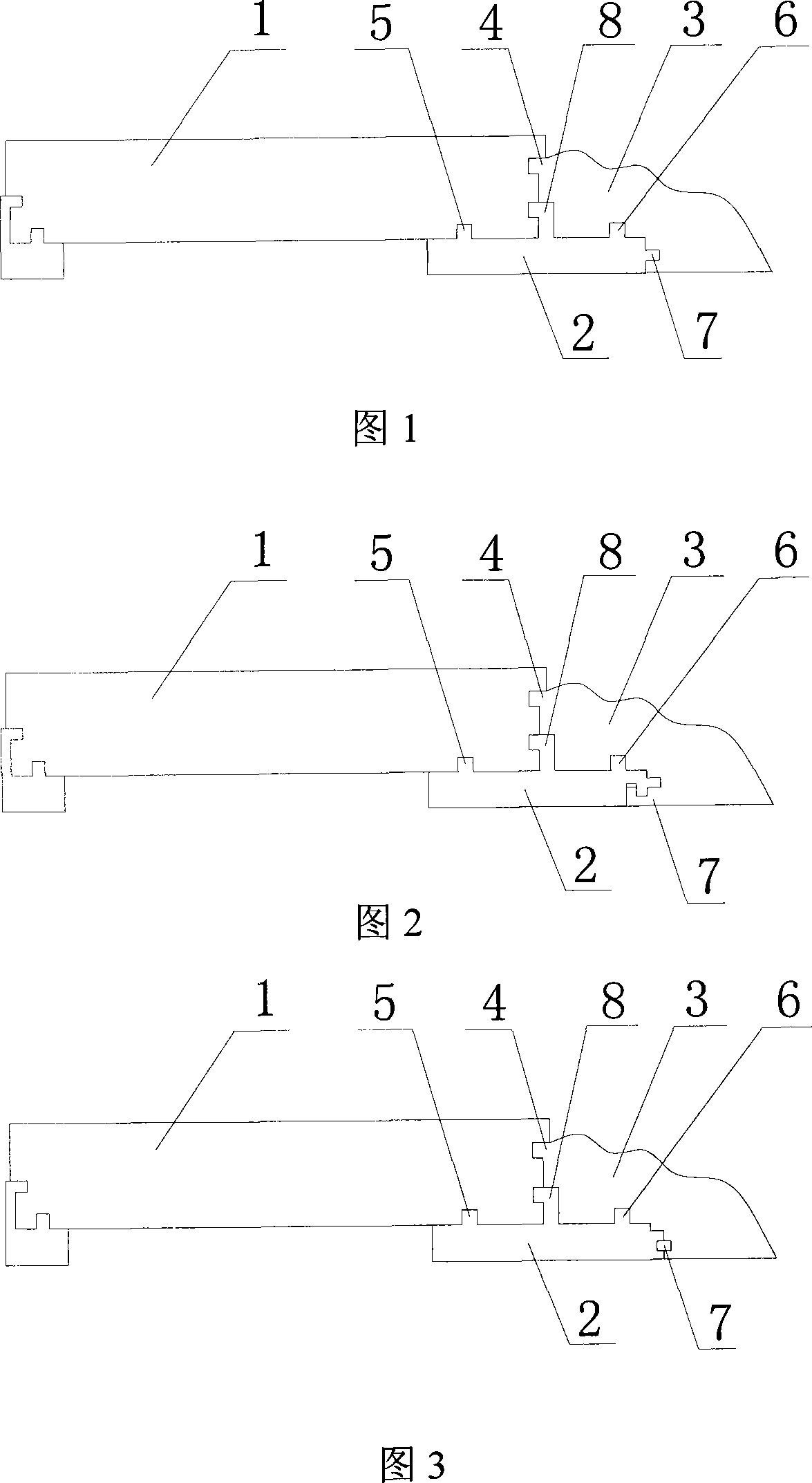
[0017] Embodiment 1: The present invention is used for the connection of edge strips. With reference to FIGS. Connected by tenon and groove 4, the keel is located under the slat 1 and the edge strip 3, and the upper surface of the keel 2 is respectively provided with a strip connector 5 and an edge strip connector 6, and a strip connector 5 and an edge strip connector 6 are respectively matched with the corresponding connecting grooves on the back of the slats and the edge-wrapping strips, and the sides corresponding to the keel 2 and the edge-wrapping strips 3 are provided with a side connecting body 7, which can be a groove, and the side connecting body 7 can be a groove. The connecting part on the inner side of the strip 3 can be a protrusion, and the above-mentioned groove matches the protrusion; the side connecting body 7 of the above-mentioned keel can also be a protrusion, and the connecting part on the inner side of the edge-wrapping strip 3 is a groove , the above-men...

Embodiment 2

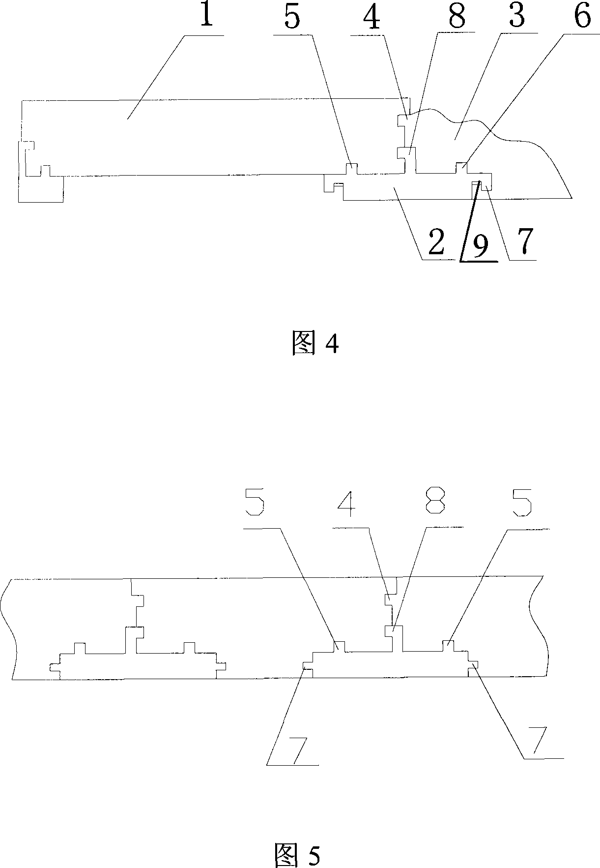
[0020] Embodiment 2, the present invention is used for connection between slats, see FIG. 4 . The present invention includes strips 1 and keels 2, the corresponding inner surfaces of the adjacent two panels 1 are connected by tongue and groove 4, the keels are located under the adjacent two panels 1, and the upper surfaces of the keels 2 are respectively provided with strips for connection. body 5, the strip connecting body 5 is respectively matched with its corresponding connection groove located on the back of two adjacent boards, the side of the keel 2 corresponding to the strip 1 is provided with a side connecting body 7, and the side connecting body 7 is located at the corresponding side The connection grooves on the inner side of the batten 1 match. The strip connecting body 5 and above can prevent the strip 1 from detaching along the direction of the strip surface; the above-mentioned side connecting body 7 can prevent the strip 1 from tilting to the side.

[0021] In ...


PUM


Abstract

A splice-type decorative plate comprises slats and joists. Lateral sides of two adjacent slats are connected by mortises, the upper surfaces of the joists are provided with slat connecting bodies which respectively match with connecting grooves, opposite to the slat connecting bodies, on the back faces of the slats. The splice-type decorative plate is characterized in that the opposite lateral sides of the joists and the slats are provided with lateral side connecting bodies which match with connecting portions, opposite to the lateral side connecting bodies, on the inside surfaces of the slats. The splice-type decorative plate of the invention is simple in structure and convenient in splice installation. As a unique splice means is employed, the slats are enabled to be firmly fixed on the joists and hard to come off, simultaneously the splice-type decorative plate further has the advantages of non-deformation and non-tilting, capability of repetitive dismantling and convenient maintenance. The splice-type decorative plate is adaptable to decoration for decoration positions of connections of floor edge lines, base molding lines, door and window frames and panel faces of combination furniture, wrapping lines of mirror frames or picture frames and wall top or others and the like.

Description

technical field [0001] The invention relates to a decorative board, in particular to a spliced ​​decorative board which is easy to install and can be disassembled repeatedly. Background technique [0002] Traditional decorative boards are generally divided into different shapes by wooden boards according to different needs, and the boards are nailed to the surface or edge of the article to be decorated. This decoration method is easy to cause damage to the decoration items, and the overall aesthetics and mutual versatility are poor. In order to solve the above problems, the applicant once applied to the China Patent Office on November 2, 2006 for an invention patent named "Combined Decorative Strip", the patent number is 200610124914.4. Although this patent solves the above problems, due to The positioning is unreasonable and there is a defect that it is easy to fall off. Contents of the invention [0003] The purpose of the present invention is to solve the shortcomings...

Claims


Application Information

Patent Timeline
Patent Type & Authority Applications(China)
IPC IPC(8): F16S1/02E04F13/07E04F13/076E04F19/02F16B12/00
Inventor 李新发
Owner 李新发
Learn More