Discharge lamp

A discharge lamp and cathode technology, which is applied in the field of xenon lamps, can solve the problems of high brightness of the light source and reduced light quantity, and achieve the effect of stabilizing the glow point and high brightness of the glow point.

Active Publication Date: 2008-08-06
USHIO DENKI KK
View PDF1 Cites 3 Cited by
  • Summary
  • Abstract
  • Description
  • Claims
  • Application Information

AI Technical Summary

Problems solved by technology

However, if the distance between the cathode 4 and the anode 5 is increased or the diameter of the tip of the tip portion 22 is increased, the expansion

Method used


Image

  • Discharge lamp
  • Discharge lamp
  • Discharge lamp

Examples


Embodiment Construction

[0027] The first embodiment of the present invention will be described. Fig. 1 is an explanatory cross-sectional view showing the structure of a discharge lamp 1 of the present invention.

[0028] This discharge lamp 1 includes a bulb made of quartz glass including an arc tube 2 and a sealed tube 3 , and a cathode 4 and an anode 5 provided to face each other inside the arc tube 2 .

[0029] Xenon gas is sealed inside a substantially spherical arc tube 2 , and sealing tubes 3 are provided integrally and continuously at both ends of the arc tube 2 . The anode 5 and the cathode 4 are respectively fitted to the tip of an electrode rod 6 made of tungsten. A holding cylinder 7 made of quartz glass is arranged inside the sealed tube 3 on the arc tube 2 side, and an electrode rod 6 supporting the anode 5 and the cathode 4 is inserted through a through hole formed in the center of the holding cylinder 7 . The reduced portion is formed by heating the sealing tube 3 in which the holdin...


PUM

PropertyMeasurementUnit
Lengthaaaaaaaaaa

Abstract

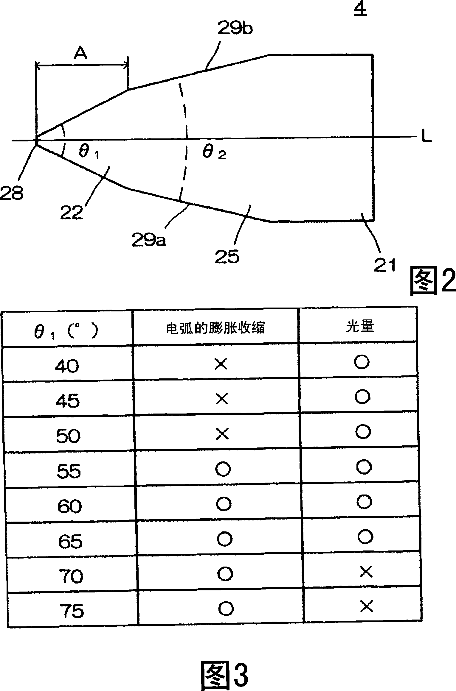
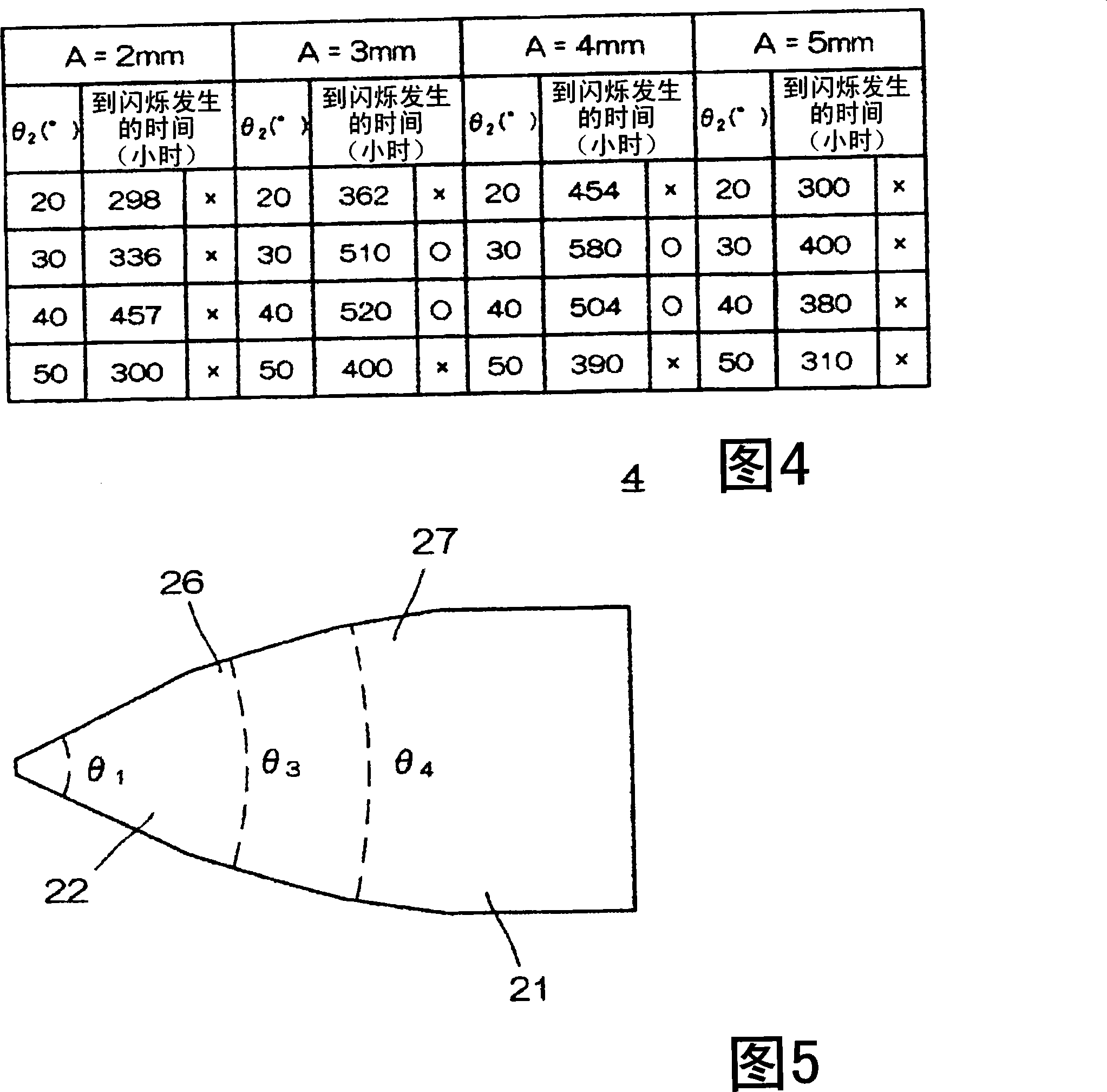
A discharge lamp includes a cathode and an anode which face each other in an arc tube, wherein the cathode is made of tungsten in which thorium oxide is doped. The cathode has a cylindrical body portion, a tip portion having a cone shape, and a middle portion formed between the body portion and the tip portion, wherein an angle θ1 of the tip portion is set to a range of 55 degrees≰θ1≰65 degrees, and an angle θ2 formed by side faces of the middle portion is smaller than that of the tip portion.

Description

technical field [0001] The present invention relates to a xenon lamp used as a light source in a projector using, for example, DLP (registered trademark) (Digital Light Processing: Digital Light Processing) technology. Background technique [0002] Fig. 6 is a diagram showing a structure disclosed in JP 2005-142071 A as a conventional discharge lamp. The discharge lamp 1 includes a bulb made of a quartz glass luminous tube 2 and a sealed tube 3 , and a cathode 4 and an anode 5 provided to face each other inside the luminous tube 2 . The cathode 4 and the anode 5 are supported by a tungsten electrode rod 6 . In addition, a holding cylinder 7 made of cylindrical quartz glass having a through-hole extending in the axial direction is fixedly provided inside the sealed tube 3 . The electrode rod 6 is inserted and held in the holding cylinder 7 and is sealed in the sealed tube 3 with a high-low seam joint glass 8 . The electrode rod 6 protrudes and extends from the outer end of...

Claims


Application Information

Patent Timeline
IPC IPC(8): H01J61/04H01J61/073
CPCH01J61/0735H01J61/0732H01J61/86
Inventor 菊池康郎藤名恭典
Owner USHIO DENKI KK
Why Eureka
Try Eureka