Integrated power capacitor

A power capacitor, integrated power technology, applied in multiple fixed capacitors, structural fixed capacitor combination, reactive power compensation and other directions, can solve the problems of large inrush current, short service life, etc. The effect of convenient on-site maintenance

Inactive Publication Date: 2010-06-02
季小龙
View PDF3 Cites 0 Cited by
  • Summary
  • Abstract
  • Description
  • Claims
  • Application Information

AI Technical Summary

Problems solved by technology

[0005] In order to overcome the disadvantages of large inrush current and short service life of the existing power capacitors during switching, the present invention provides an integrated power capacitor with no inrush current during capacitor switching and prolonging service life

Method used


Image

  • Integrated power capacitor
  • Integrated power capacitor
  • Integrated power capacitor

Examples


Embodiment Construction

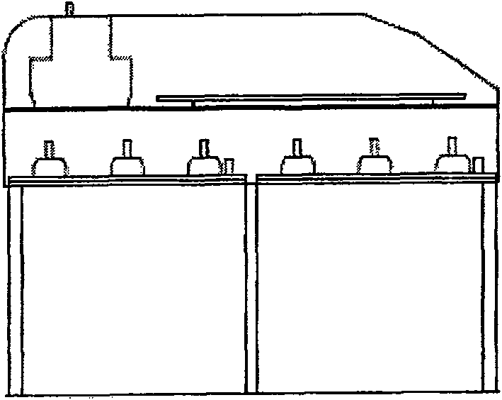
[0033] The present invention will be further described below in conjunction with the accompanying drawings.

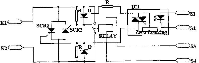
[0034] refer to Figure 1 to Figure 6 , an integrated power capacitor, comprising a housing on which a measurement and control device, a capacitor switching switch and a protection circuit are installed, and a power capacitor is installed below the housing; the switching switch is a composite switch, which includes SCR switches SCR1, SCR2 and magnetic latching relay RELAY, the SCR switches SCR1, SCR2 are connected in parallel with the nodes of the magnetic latching relay RELAY, and the SCR switches are two anti-parallel thyristors, so The trigger terminal of the thyristor is connected to control the trigger chip IC1 that triggers the thyristor after the voltage crosses zero, and the trigger chip IC1 is connected through S1 and S2, and the magnetic latching relay is connected through S3 and S4 to detect the three-phase circuit and judge whether A microcontroller that n...


PUM


Abstract

An integration power capacitor comprises a shell body, wherein, a measurement and control device, a capacitor throw cut-off switch and a protective circuit are arranged on the upper side of the shellbody, a power capacitor is arranged on the lower side of the shell body; the throw cut-off switch is a compound switch comprising thyristor switches and a magnetic latching relay; the thyristor switches are parallel connected with the node of magnetic latching relay, the thyristor switches are two inverse parallel thyristors, trigger ends of the thyristors are connected with trigger chips used tocontrol to trigger thyristors after voltage zero crossing, the trigger chips and the magnetic latching relay are connected to detect a three-phase circuit and determine whether switching a single chipof the capacitor is needed. The integration power capacitor prolongs the service life and does not have the impulse current when the capacitor switching.

Description

technical field [0001] The invention relates to a power capacitor. Background technique [0002] Most of the electrical loads in the grid, such as motors and transformers, are inductive loads, and corresponding reactive power must be provided to these devices during operation. After installing reactive power compensation equipment such as shunt capacitors in the grid, it can provide reactive power consumed by inductive reactance, reducing the reactive power provided by the grid power supply to the inductive load and transmitted by the line, due to the reduction of reactive power in the grid Therefore, it can reduce the power loss caused by the transmission of reactive power in lines and transformers, and perform reactive power compensation. Reactive power compensation can improve the power factor, which is a loss reduction and energy saving measure with less investment and quick results. [0003] Commonly used reactive power compensation methods in the power grid include: ...

Claims


Application Information

Patent Timeline
Patent Type & Authority Patents(China)
IPC IPC(8): H02J3/18H01G4/38H01G4/40
CPCY02E40/30
Inventor 陈胜勇刘东季小龙
Owner 季小龙
Why Eureka
Try Eureka