
A method for forming the standard voltage of under-voltage lock circuit and its circuit

An undervoltage lockout circuit and reference voltage technology, applied in electrical components, regulating electrical variables, output power conversion devices, etc., can solve the problems of drift, lock threshold voltage drift, built-in hysteresis of comparators, etc., and achieve stable hysteresis. , the effect of locking the threshold voltage stability

Inactive Publication Date: 2008-08-06
VIMICRO CORP
View PDF0 Cites 25 Cited by
  • Summary
  • Abstract
  • Description
  • Claims
  • Application Information

AI Technical Summary

Problems solved by technology

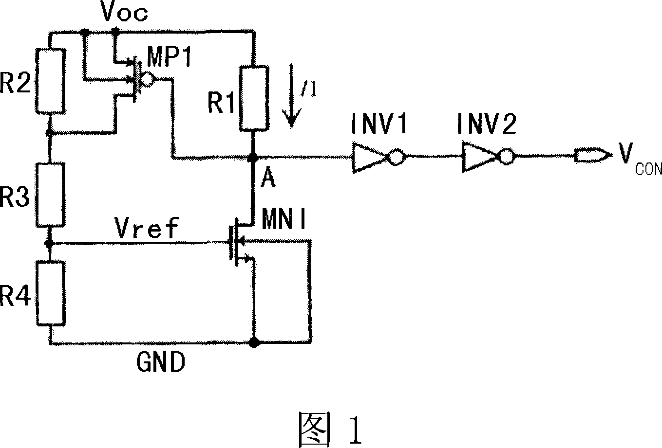
[0007] The reference voltage VREF generated by the traditional undervoltage lockout circuit will change with the temperature, and the bias current I1 will change with the power supply voltage VBAT, and considering that the transistor parameters are affected by temperature and parasitic parameters, the The built-in hysteresis of the comparator has serious drift, which directly causes the lock threshold voltage to drift, so that the operating voltage range of the power supply cannot be strictly controlled

Method used


Image

  • A method for forming the standard voltage of under-voltage lock circuit and its circuit
  • A method for forming the standard voltage of under-voltage lock circuit and its circuit
  • A method for forming the standard voltage of under-voltage lock circuit and its circuit

Examples


Embodiment Construction

[0025] The method and circuit of the present invention will be described in detail below.

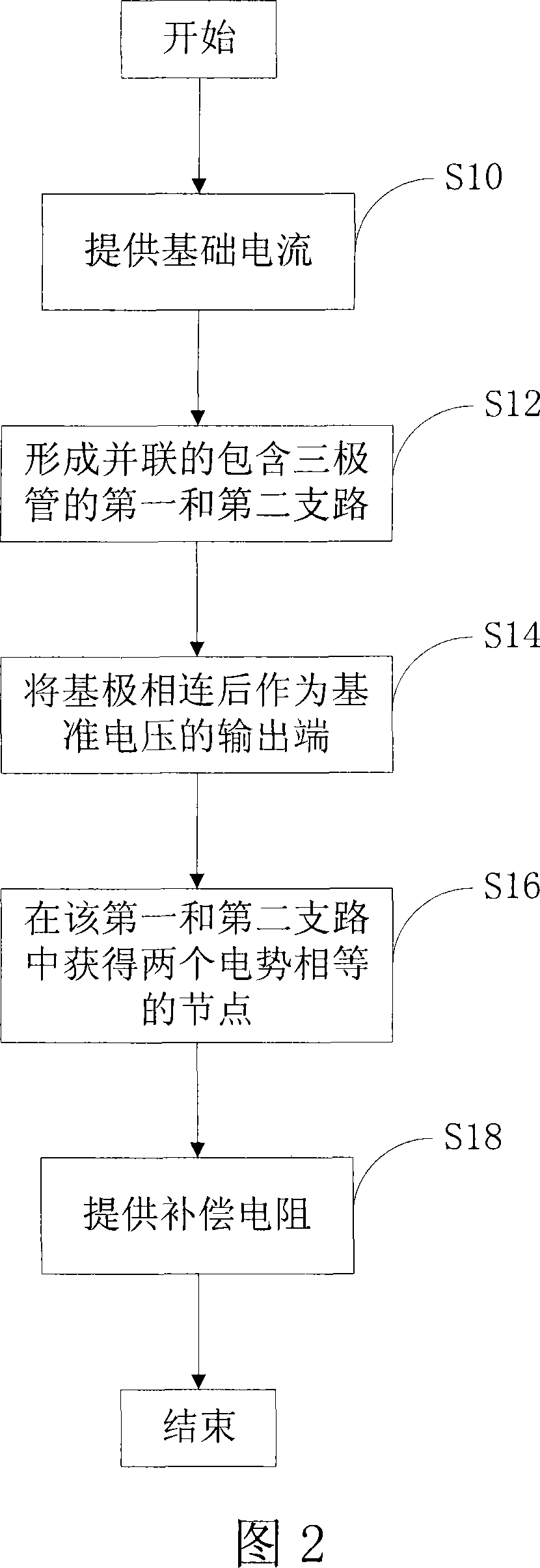
[0026] Referring to FIG. 2, firstly, the present invention needs to provide a reference current source, such as step S10.

[0027] Secondly, in step S12, the above-mentioned current is provided to two parallel branches, wherein each of the two branches has a triode element, so as to use the voltage difference on their PN junctions to generate a positive temperature coefficient current. In particular, in the present invention, the bases of the two triodes are connected and used as the output terminals of the reference voltage, as in step S14.

[0028] Meanwhile, in step S16, the present invention needs to use an error amplifier connected across the two branches to ensure that equal potential nodes can be obtained on the two branches.

[0029] In order to make the reference voltage formed by the present invention compensated by temperature, so that the reference voltage of the present i...


PUM


Abstract

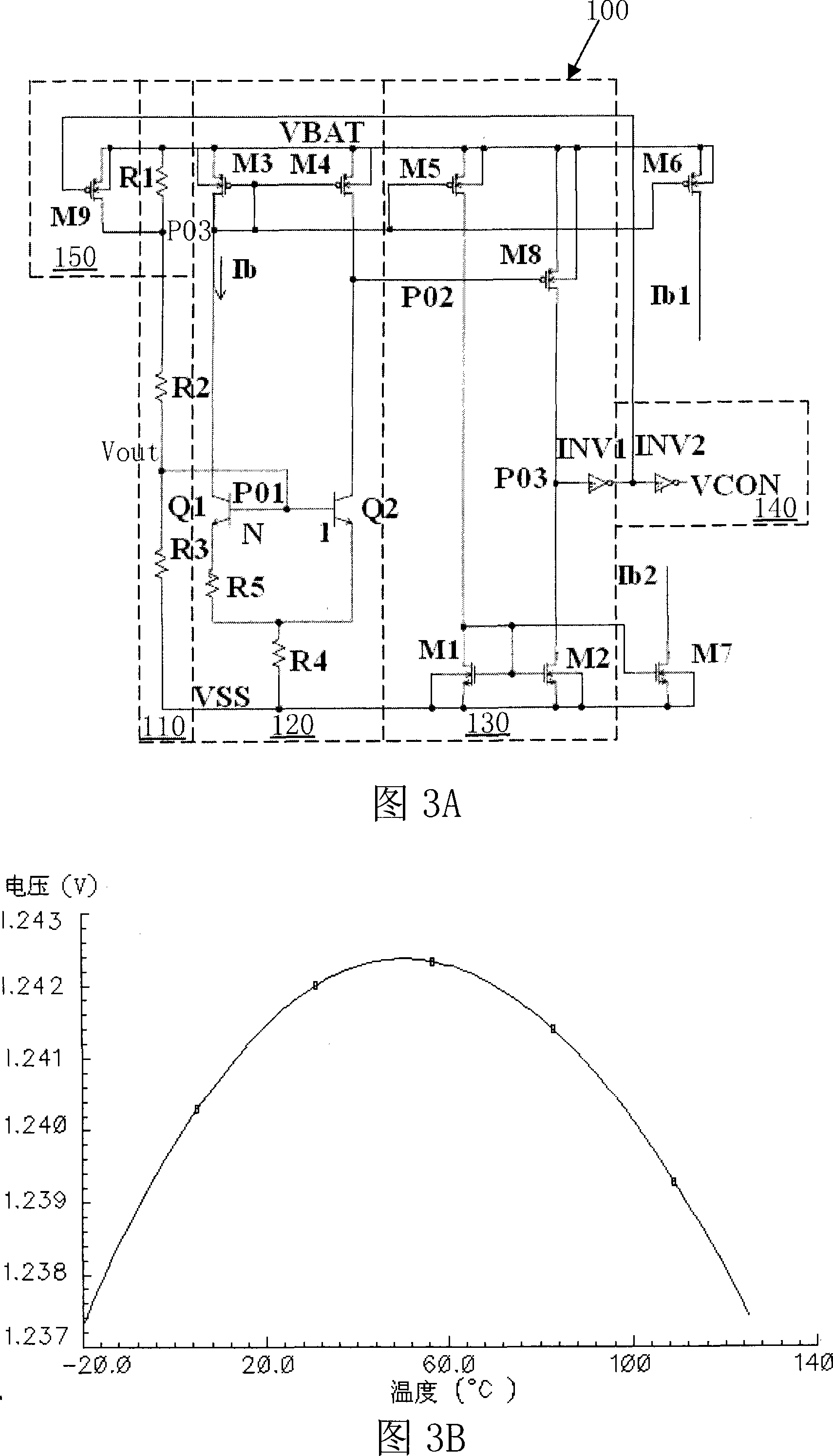
The invention discloses an under-voltage lockout circuit of a voltage reference self-produced. The method for forming the voltage reference to compare with a sampling voltage comprises the steps of: providing a basic current supply in a power return circuit; forming a first branch circuit and a second branch circuit which are in parallel, wherein each branch circuit comprises at least one triode which is used to form a current with a positive temperature coefficient; connecting the base electrode of a first triode with the base electrode of a second triode to output the reference voltage; providing an error amplifier for clamping which is connected astride between the first branch circuit and the second branch circuit to obtain a first node and a second node in equal potential; providing a compensation resistance which is used for the reference voltage to enable the basic current with the positive temperature coefficient outputted by the parallel branches produce a voltage drop on the compensation resistance in proportion to the temperature. Due to the temperature compensation on the voltage reference self-produced, the stability of locking a threshold voltage and a lag is ensured.

Description

technical field [0001] The invention relates to an undervoltage lockout circuit, in particular to a method for forming a reference voltage for comparison with a power supply sampling voltage and the undervoltage lockout circuit thereof. Background technique [0002] In the management chip of the DC-DC power supply, voltage stability is particularly important, so it is necessary to integrate an undervoltage lockout circuit inside the chip to improve the reliability and safety of the power supply. For other integrated circuits, in order to improve the reliability and stability of the circuit, the undervoltage lockout circuit is also very important. [0003] The essence of the undervoltage lockout circuit is to output a control signal at the same time by comparing a reference voltage and the sampling voltage of the power supply. The basic schematic diagram of a traditional undervoltage lockout circuit is shown in Figure 1. The circuit includes a voltage sampling circuit; a co...

Claims


Application Information

Patent Timeline
Patent Type & Authority Applications(China)
IPC IPC(8): H02M1/00H02M1/32G05F3/26
Inventor 郑儒富
Owner VIMICRO CORP
Learn More