
Injection-moulding device with needle valve nozzle and guide bush

A technology for injection molding equipment and sleeves, applied in the field of injection molding equipment, can solve problems such as damage to the sealing effect, pollution of tools, pollution of closed needle parts, etc., and achieve the effect of simplifying the structure and simplifying the installation.

Inactive Publication Date: 2008-08-06
GUENTHER HEISSKANALTECHNIK GMBH
View PDF4 Cites 2 Cited by
  • Summary
  • Abstract
  • Description
  • Claims
  • Application Information

AI Technical Summary

Problems solved by technology

[0005] Despite such an optimized configuration of the sealing system, due to the relatively high pressure in the tool and due to the lifting movement of the needle, it cannot be avoided that the material to be processed seeps through the guide sleeve or the sealing sleeve
The result is material loss
In addition, material residues contaminate not only the closing needle but also the tool, which not only impairs the sealing effect, but may hinder the opening and closing movement of the closing needle over a long period of time
Expensive cleaning or maintenance work is unavoidable

Method used


Image

  • Injection-moulding device with needle valve nozzle and guide bush
  • Injection-moulding device with needle valve nozzle and guide bush

Examples


Embodiment Construction

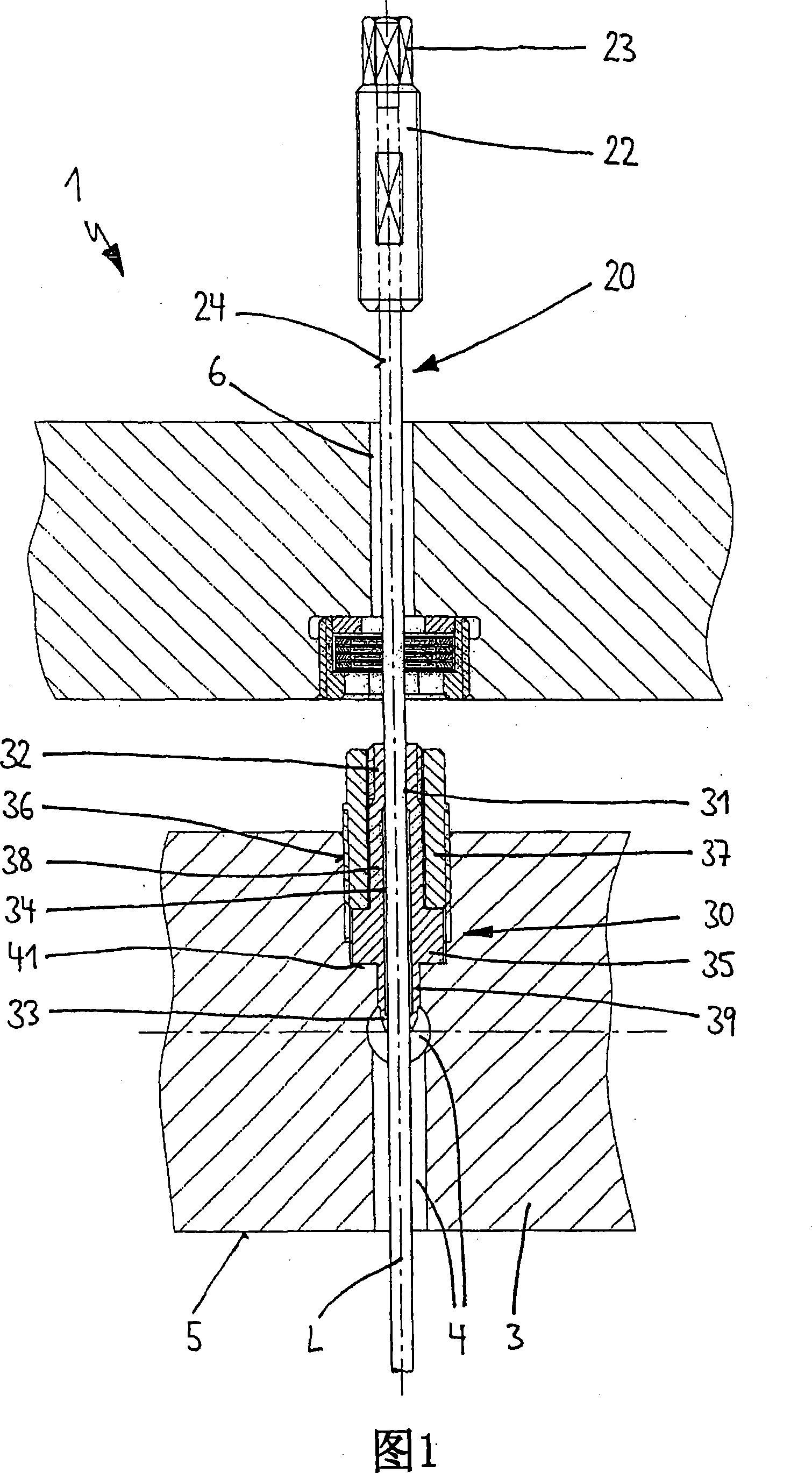
[0027] The injection molding plant shown generally at 1 in FIG. 1 is used for the production of mold parts from flowable substances, for example from plastic melts. The injection molding machine 1 has a clamping plate 2 and a distribution plate 3 parallel to the clamping plate 2 , forming a system of flow channels 4 in the distribution plate 3 . The flow channels 4 each open into needle shut-off nozzles (not shown) mounted on the underside 5 of the distribution plate 3 .

[0028] Each needle shut-off nozzle has a preferably externally heated nozzle body (also not shown), in which a material tube is formed centrally with respect to the longitudinal axis L as a continuation of the flow channel 4 . The flow channel 4 ends in a spray head, which forms a nozzle outlet on the end side, through which the material to be processed is fed through a casting opening to a separable mold insert (likewise not shown).

[0029] For opening and closing the casting opening, preferably formed in...


PUM


Abstract

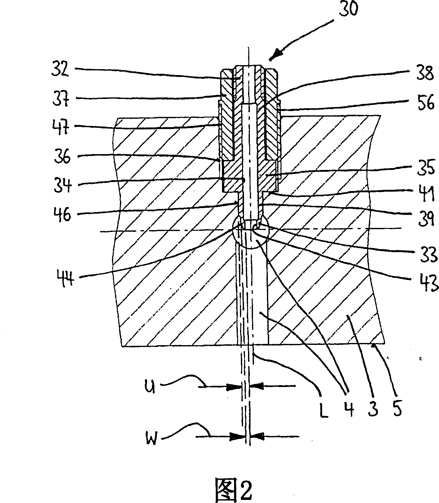
Injection molding device (1) with: distribution plate (3) in which at least one flow channel (4) for flowable material is formed; at least one needle closing nozzle by which the nozzle is closing , the flowable material can be fed to the separable mold insert under the guidance of the flow channel; at least one closing needle (20), the closing needle (20) at least partially moves longitudinally through the flow channel and can be in an open and closed position by means of a drive member; and a guide sleeve (30) which allows the closure needle (20) to pass and seals the closure needle (20). The guide sleeve has a region which surrounds the closing needle with little movement play and which is located at least partially in the flow channel. This region thus has a contact surface for the flowable material, which is at least partially located within the flow channel. The flowable material flows around the region and all sides of the interface (44).

Description

technical field [0001] The invention relates to an injection molding machine with a needle shut-off nozzle according to the general concept of claim 1 . Background technique [0002] The needle shut-off nozzle is inserted into the injection molding machine in order to supply the flowable mass at a predeterminable temperature and under high pressure into the separable mold insert. Needle closing nozzles usually have a pneumatically or hydraulically driven closing needle which periodically opens and closes the casting opening in the mold insert. This enables the most precise material dosing possible, especially in fast shot sequences. However, it is also possible to inject the flowable mass in sections, for example in cascade casting. [0003] Each closing needle is installed axially displaceably in the tool-side area of ​​the injection molding device and preferably centrally through the flow channel for the substance to be processed in the nozzle-side area (see for example ...

Claims


Application Information

Patent Timeline
IPC IPC(8): B29C45/28B22D17/20B29C45/33
CPCB29C45/2806B29C2045/2889B29C45/23B29C45/28
Inventor 赫伯特·君特
Owner GUENTHER HEISSKANALTECHNIK GMBH
Learn More