Linear actuator, valve apparatus and pump apparatus using the same

A technology of pump devices and active valves, applied to pumps with flexible working elements, parts of pumping devices for elastic fluids, pumps, etc., to achieve the effects of preventing backflow, suppressing deviation, and uniform discharge performance

Inactive Publication Date: 2008-08-13
SANKYO SEIKI MFG CO LTD +1
View PDF5 Cites 2 Cited by
  • Summary
  • Abstract
  • Description
  • Claims
  • Application Information

AI Technical Summary

Problems solved by technology

However, there are currently no concrete proposals for a pump unit with such characteristics

Method used


Image

  • Linear actuator, valve apparatus and pump apparatus using the same
  • Linear actuator, valve apparatus and pump apparatus using the same
  • Linear actuator, valve apparatus and pump apparatus using the same

Examples


Embodiment Construction

[0074] First, a linear actuator to which the present invention is applied will be described with reference to the drawings.

[0075] (the whole frame)

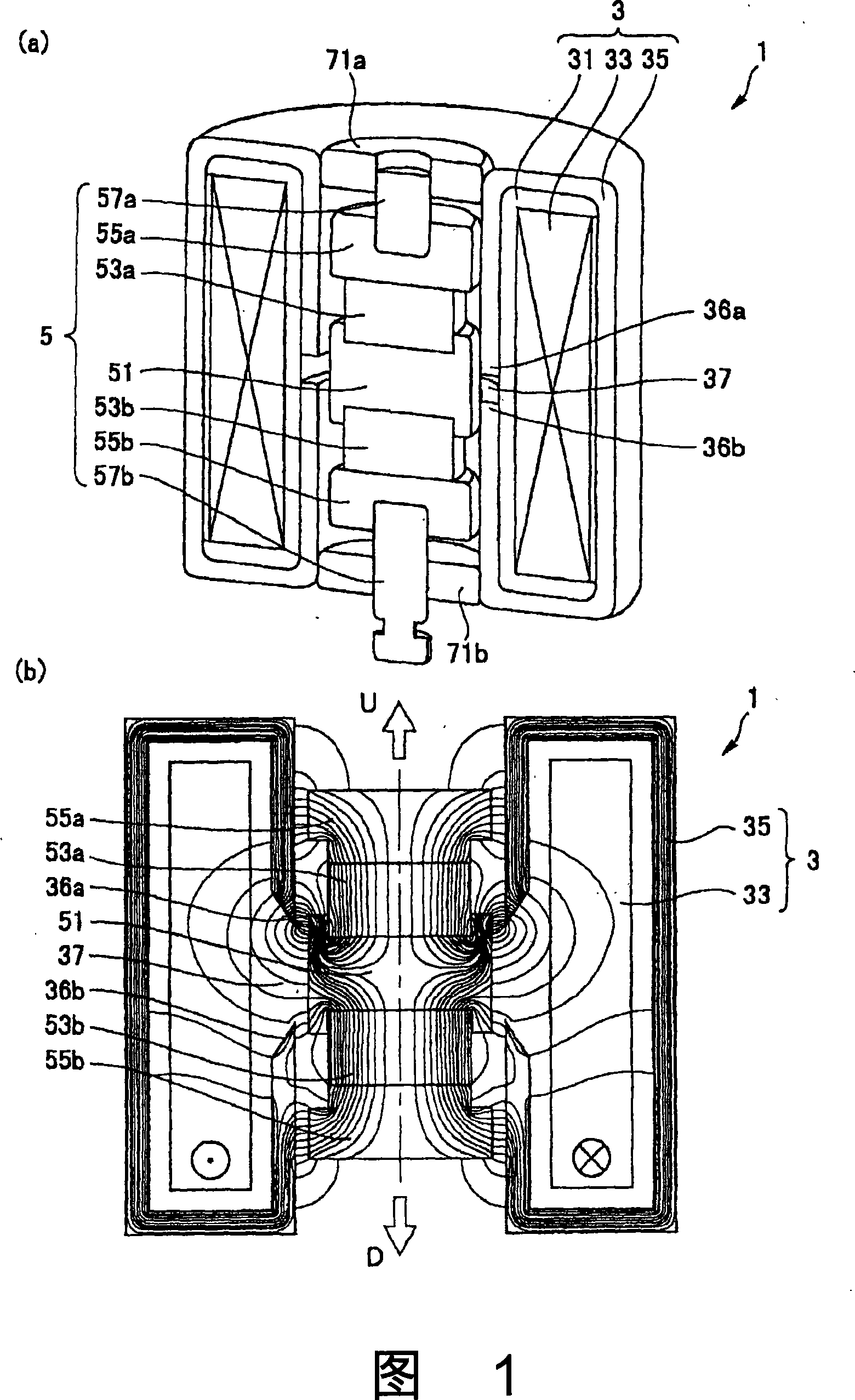
[0076] Fig. 1(a) and (b) are explanatory diagrams showing the main part of the linear actuator to which the present invention is applied, cut along the axial direction and seen from obliquely above, and a diagram showing the magnetic force lines of the linear actuator, respectively. Illustrating.

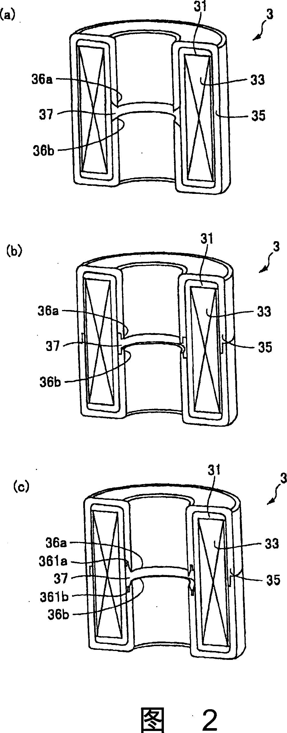
[0077] In Fig. 1 (a), (b), the linear actuator 1 of this form is used for supplying various fluids, such as a valve device and a compressor device, and has: a cylindrical fixed body 3, disposed on the A substantially cylindrical movable body 5 inside the fixed body 3 . The fixed body 3 includes: a coil 33 annularly wound on the reel 31; from the outer peripheral surface of the coil 33, the two sides in the axial direction of the coil 33, one front end 36a and the other front end 36b are placed between the coils. The inner periphera...


PUM


Abstract

A pump device is disclosed, characterized in that the pump device main body comprises a inflow channel communicated with a inflow hole, a inflow side active valve configured within the inflow channel, a pump chamber connected with the inflow channel, a pump mechanism configured within the pump chamber, a plurality of outflow channels which stretch from the pump chamber and are respectively communicated with a plurality of outflow holes, and outflow side active valves which are respectively configured within the plurality of outflow channels, the outflow side active valves are configured around the pump chamber in a planar shape.

Description

[0001] This application is a divisional application for an invention patent with an application date of November 30, 2005, an application number of 200510128806.X, and a title of "Linear Actuator and Valve Device and Pump Device Using It". technical field [0002] The present invention relates to a linear actuator and a valve device using the linear actuator. The present invention also relates to a pump device, especially a pump device with an inlet and a plurality of outlets on the body of the pump device. Background technique [0003] Conventionally, as a linear actuator used in a valve device in a pump, etc., there is a structure that uses an electromagnet instead of a magnet. than the problem of a sharp decrease. For a short time, the thrust can be increased by inputting a large current to the coil, but continuous operation with a large current input to the coil will cause significant heat generation and be dangerous. [0004] For this reason, there is a proposal of a ...

Claims


Application Information

Patent Timeline
Patent Type & Authority Applications(China)
IPC IPC(8): F04B43/04F04B53/10F04B53/00H01M8/04H01M8/00
CPCY02E60/50
Inventor 村松健次横沢满雄高沢清继杉原广志
Owner SANKYO SEIKI MFG CO LTD
Why Eureka
Try Eureka