LED mine lamp using non-imaging optical system

A non-imaging optics, LED miner's lamp technology, applied in the field of miner's lamp, can solve the problem of unsatisfactory light distribution effect, achieve good visual effect, improve the utilization rate of light energy, and the effect of accurate illuminance distribution

A non-imaging optics, LED miner's lamp technology, applied in the field of miner's lamp, can solve the problem of unsatisfactory light distribution effect, achieve good visual effect, improve the utilization rate of light energy, and the effect of accurate illuminance distribution

CN101240886AInactive Publication Date: 2008-08-13UNIV OF SHANGHAI FOR SCI & TECH

Image

  • LED mine lamp using non-imaging optical system

Examples


Embodiment Construction

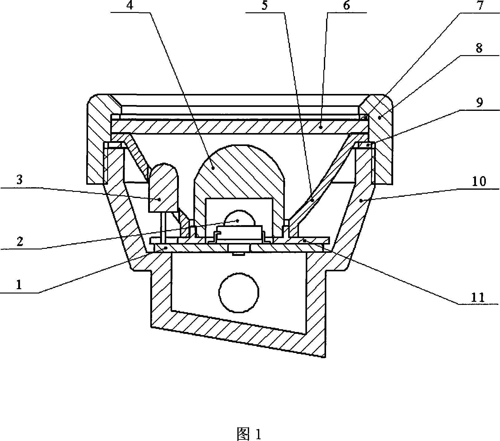
[0013] As shown in Figure 1, the LED miner's lamp using a non-imaging optical system is composed of a non-imaging optical system, a housing component and a lighting circuit component. Wherein, the non-imaging optical system comprises an aspheric compound lens 4, a free-form surface reflector 5 and a base 11, the aspheric compound lens 4 is located in the internal space of the free-form surface reflector 5, the aspheric compound lens 4, the free-form surface reflector 5 They are respectively fixed on the base 11; the lighting circuit components include a high-power LED main light source 2, an auxiliary light source 3 and a circuit board 1, and the high-power LED main light source 2 and the auxiliary light source 3 are respectively welded and fixed on the circuit board 1; the circuit board 1 is located under the base 11 and is connected and fixed together with the base 11, so that the main light source 2 on the circuit board 1 is located in the cylindrical cavity of the aspheric ...


PUM


Abstract

The present invention provides a LED miner's lamp using nonimaging optics, including a nonimaging optics, a casing part and a lighting circuit part, miner's lamp adopting aspherical composite lens and free surface reflector form the optical system, since the convexity of the composite lens and the reflecting surface of the reflector are free surfaces designed according to light distributing requirement, and optical line adjacent to the optical axis and optical line far from the optical axis are respectively controlled by the composite lens and free surface reflector, thus the size and the lighting distribution of the lighting area is more exact controlled, this improves utilization rate of the light energy and bas better visual effect.

Description

technical field [0001] The invention relates to a miner's lamp using LED as a light source, in particular to an LED miner's lamp using a non-imaging optical system. Background technique [0002] With the continuous improvement of the light efficiency of high-power LEDs, it has become possible to use LEDs as light sources for miner's lamps. In order to improve the utilization rate of the light energy of the light source, previous design schemes generally use a quadric surface (such as a paraboloid) reflector to gather light, or use a quadric surface reflector to cooperate with a spherical lens to achieve light energy distribution. The method of only using a quadric surface reflector cannot control the optical path of light near the optical axis, and a simple quadric surface cannot meet the light distribution requirements in many cases. In the method of using a parabolic reflector to cooperate with a spherical lens, the solution of installing the lens at the position of the l...

Claims


Application Information

Patent Timeline
13 Aug 2008
Publication
CN101240886A
IPC
F21V13/04; F21V5/04; F21V7/04; F21W131/402; F21Y101/02; F21Y113/00; F21Y115/10
Inventors
施伟斌; 陈祥熙