Infrared focal plane array image-forming demonstration system

A technology of infrared focal plane and demonstration system, applied in the field of infrared focal plane array imaging demonstration system, can solve the problem of inability to apply scanning infrared imaging test and demonstration, without real-time algorithm simulation and demonstration imaging, and inability to evaluate thermal imager design and algorithm problems such as the actual imaging effect, to achieve the effect of strong scalability, flexibility and convenience, and low development costs

Inactive Publication Date: 2008-08-13
NANJING UNIV OF SCI & TECH
View PDF0 Cites 21 Cited by
  • Summary
  • Abstract
  • Description
  • Claims
  • Application Information

AI Technical Summary

Problems solved by technology

The main disadvantages of the system are: 1. The system does not have real-time algorithm simulation and demonstration imaging functions; 2. The system cannot evaluate the actual imaging effect of the thermal imager design and algorithm; 3. The system cannot be used for scanning infrared imaging tests with demo

Method used


Image

  • Infrared focal plane array image-forming demonstration system
  • Infrared focal plane array image-forming demonstration system
  • Infrared focal plane array image-forming demonstration system

Examples


Embodiment Construction

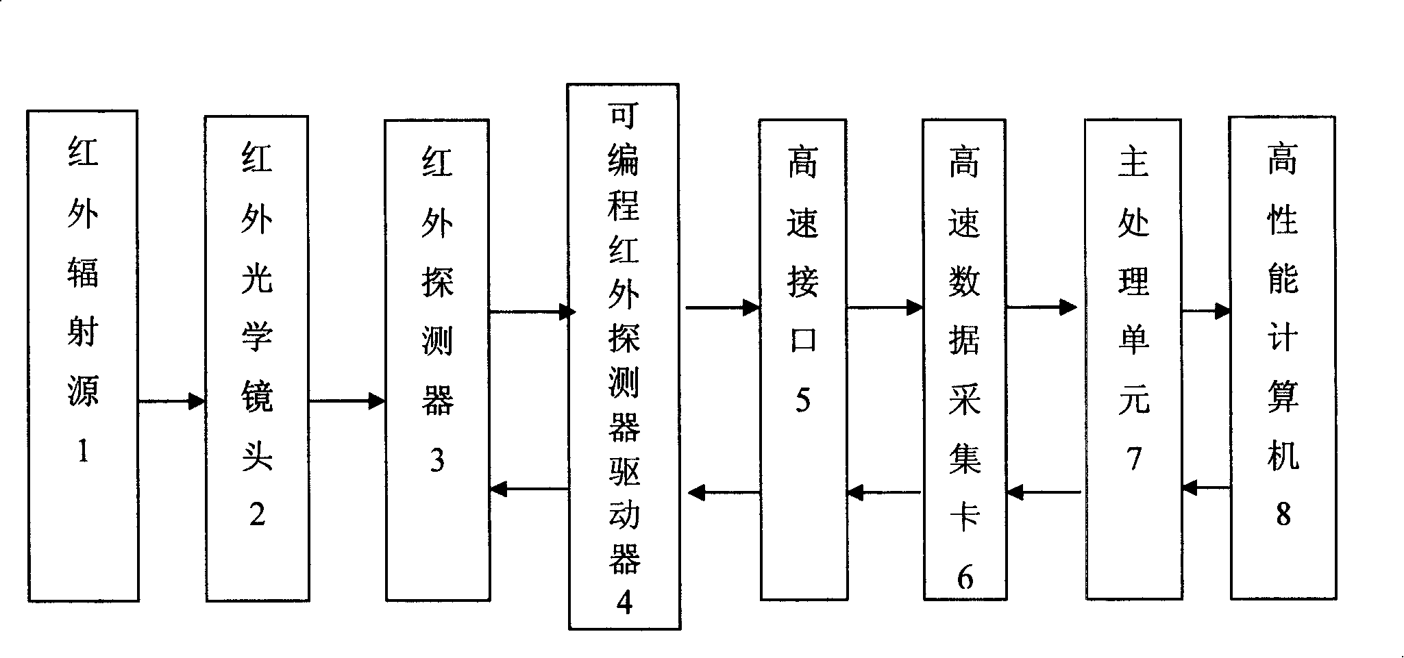
[0012] combine figure 1 , the infrared focal plane array imaging demonstration system of the present invention includes an infrared radiation source 1, an infrared optical lens 2, an infrared focal plane detector 3, a programmable infrared detector driver 4, a high-speed interface 5, a high-speed data acquisition card 6, and a main processing unit 7 and High Performance Computers 8. The infrared radiation emitted by the infrared radiation source 1 is focused on the infrared focal plane measuring device 3 through the infrared optical lens 2, and each unit on the infrared focal plane measuring device 3 is controlled by the driving and bias signals provided by the programmable infrared detector driver 4. Under the drive, the infrared radiation signal is converted into an electrical signal. The clock and trigger signal required by the programmable infrared detector driver 4 are set by the program programming of the high-performance computer 8, and are passed through the main proce...


PUM


Abstract

The invention discloses an infrared focal plane array imaging demonstrating system. Said system comprises an infrared radiating resource, infrared optical lens, an infrared focal plane detector, a programmable infrared detector driver, a high-speed interface, a high-speed data collecting card, a main processing unit and a high-functional computer. The infrared radiation is focalize on the infrared focal plane detector via the infrared optical lens; each unit on the infrared focal plane detector can convert the infrared radiating signal into electrical signal driven by driving and offset signals provided by the programmable infrared detector driver; clock and triggering signal needed by the programmable infrared detector driver is set by program programming of the high-functional computer which is transmitted to the programmable infrared detector driver by the main processing unit, high-speed data collecting card and high-speed interface. This invention enables designing stuff intuitively observe and evaluate the real imaging effect of the designed system and arithmetic and timely rectify and check the design and arithmetic, avoiding all sorts of troubles during process of system debugging.

Description

a technical field [0001] The invention belongs to infrared thermal imager technology, in particular to an infrared focal plane array imaging demonstration system. Two background technology [0002] The development of the image processing board is the key to the design of the infrared thermal imager. At present, researchers of infrared thermal imaging cameras and image processing algorithms at home and abroad have proposed a variety of algorithms, but their practicability, real-time performance and application range need to be verified by research, and there is no such corresponding algorithm evaluation demonstration in China. The system is simulated and evaluated. The existing method is to make multiple versions of the hardware circuit of the whole system, and repeatedly debug, revise and verify. The development cycle is long, the cost is expensive, and it is often unknown which part has a problem during the debugging process. In 2002, the article of MichaelA.Soel et al in...

Claims


Application Information

Patent Timeline
Patent Type & Authority Applications(China)
IPC IPC(8): G01J5/10
Inventor 陈钱顾国华屈惠明隋修宝钱惟贤王利平于雪莲柏连发白俊奇
Owner NANJING UNIV OF SCI & TECH
Why Eureka
Try Eureka