Motor and bearing supporting structure

A technology of bearing support and bearing, which is applied in the direction of casing/housing/support, structural connection, electrical components, etc., can solve problems such as difficult control of dimensional stability, shortened product life, and stuck, so as to improve product reliability and Efficiency, expanding design margin, and avoiding the effect of axial movement

Active Publication Date: 2008-08-13
DELTA ELECTRONICS INC
View PDF0 Cites 7 Cited by
  • Summary
  • Abstract
  • Description
  • Claims
  • Application Information

AI Technical Summary

Problems solved by technology

[0004] The bearing support structure 1 also has a cover body 13 that directly pushes against the bearing 12 in the axial direction. However, because the bearing support structure does not have a buffer design, the bearing 12 is prone to no force or excessive force due to variations in materials and processes, causing the bearing 12 to The inner hole shrinks or deforms, which causes the shaft S to rotate unsmoothly or even get stuck
[0005] Furthermore, the material and process variation caused by the interference fit press fit will cause the bearing 12 to be deformed or shrink due to excessive force, causing abnormal friction of the bearing 12, affecting its reliability and shortening the product life, and even the shaft S is stuck. In addition, there are disadvantages such as insufficient bonding strength by adhesive bonding, or the adhesive enters the inner hole of the bearing 12 and causes the shaft S to be stuck.
[0006] In addition, there are many deficiencies in the processing of the bushing 11. If it is molded with plastic, the investment in equipment (molding machine) is high, the cost of the mold is high, the dimensional stability is poor (easy to be deformed or softened by heat), and the reliability of temperature resistance is poor; When it is made by turning, the investment in equipment (CNC lathe) is large, the production capacity of the unit machine is poor (only about 3000 to 5000 pieces in 24 hours, 3-5Kpcs / 24Hrs), the waste of materials is large (the utilization rate is lower than 60%), and the cost is high. High and dimensional stability is not easy to control; if it is formed by hot die casting, the investment in equipment (die casting machine) is large, the mold cost is high, the dimensional stability is poor, and the precise size needs to be precision processed again and the cost is high

Method used


Image

  • Motor and bearing supporting structure
  • Motor and bearing supporting structure
  • Motor and bearing supporting structure

Examples


Embodiment Construction

[0035] A bearing support structure according to a preferred embodiment of the present invention will be described below with reference to related drawings, wherein the same elements will be described with the same reference symbols.

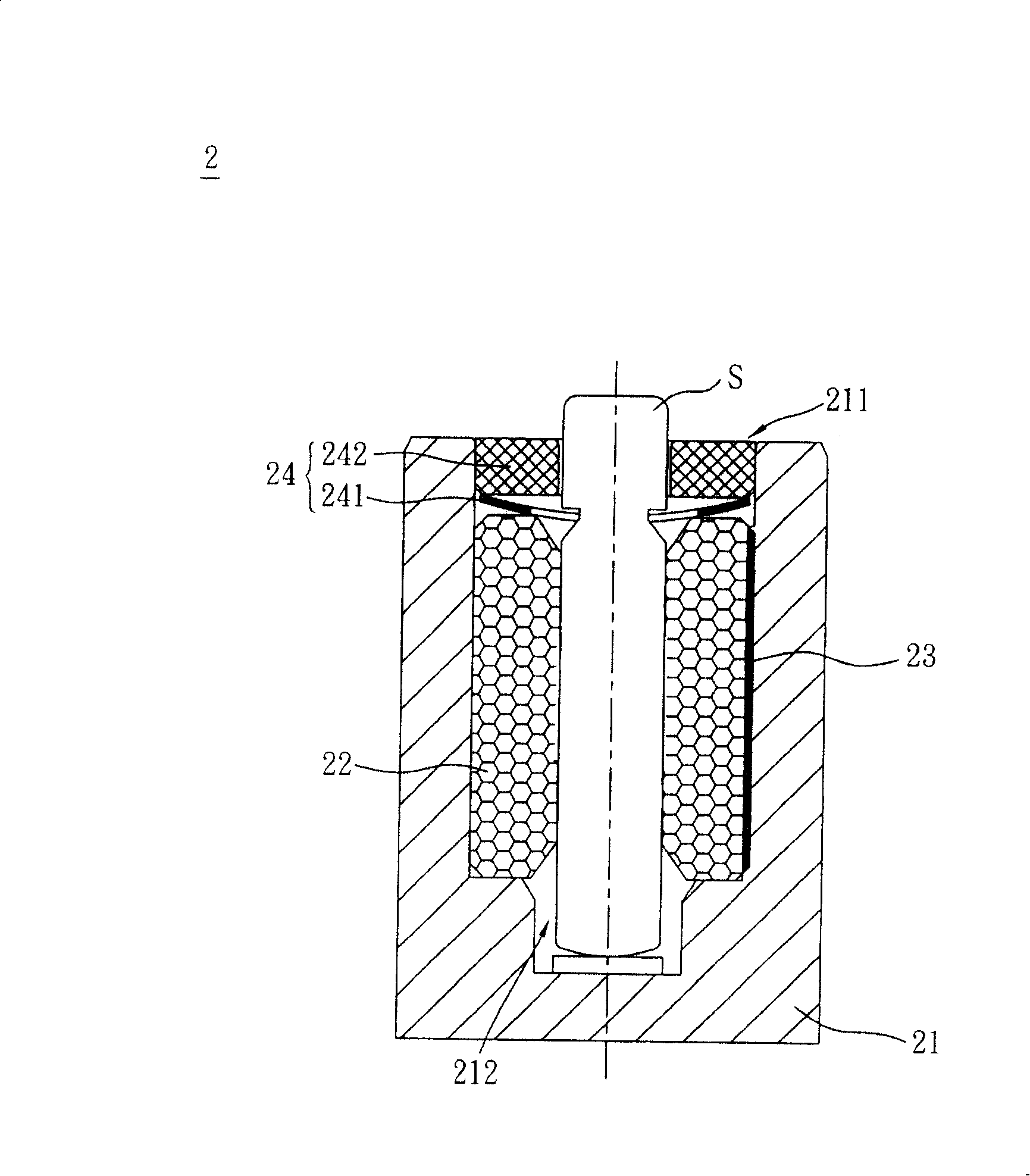
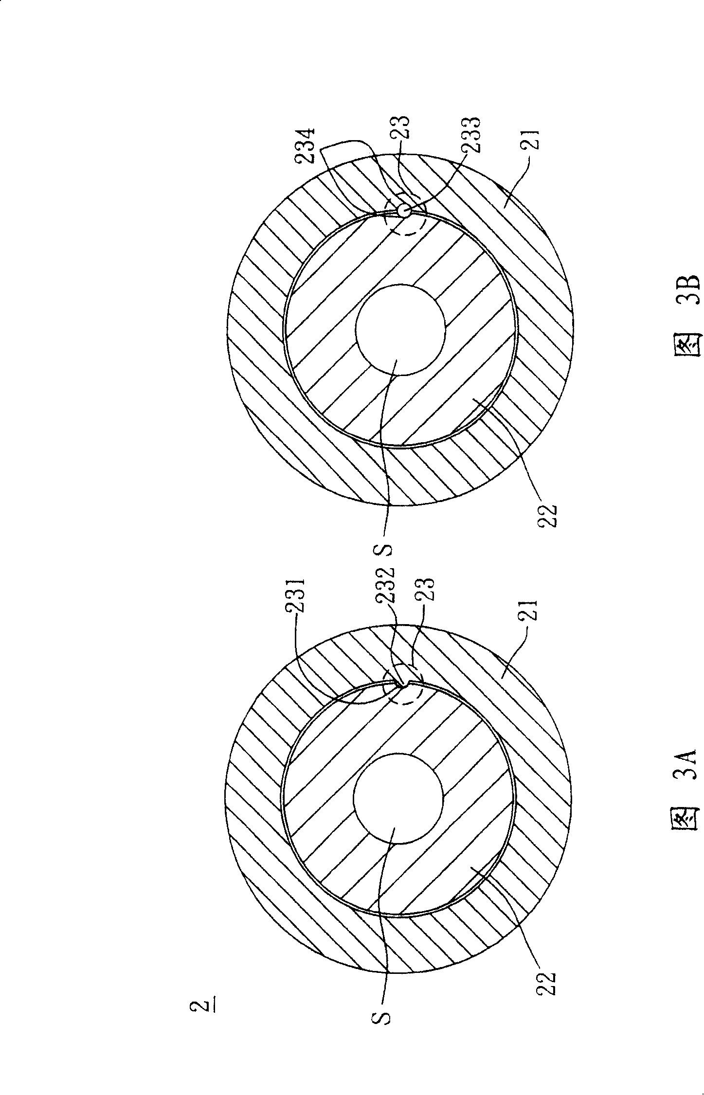
[0036] Please refer to figure 2 , a bearing support structure 2 in a preferred embodiment of the present invention includes a bushing 21 and a bearing 22 , and the bearing support structure 2 supports a rotating shaft S. Wherein, the bushing 21 has an opening 211 and an accommodating space 212 , the bearing 22 is disposed in the accommodating space 212 of the bushing 21 , the rotating shaft S passes through the bearing 22 , and the bearing 22 supports at least part of the rotating shaft S. The bearing support structure 2 also includes at least one first limiting component 23, such as a circumferential limiting component, which is arranged at the connection between the bearing 22 and the bushing 21, so as to prevent the relative rotation of the b...


PUM


Abstract

Provided is a motor and bearing support structure thereof to support a shaft. The bearing support structure includes a bushing that has an opening and a placing space, a bearing being positioned in the placing space and supporting at least part of the shaft, and at least one first restriction component being disposed where the bearing is connected with the bushing.

Description

technical field [0001] The present invention relates to a motor and its bearing support structure, in particular to a motor and its bearing support structure for fixing the bearing to avoid relative movement between the bearing and the bushing. Background technique [0002] Electronic devices with rotating parts (such as fans or hard disks) often use a driving element (such as a motor) to drive the rotating parts. The driving element has a bearing support structure for supporting a rotating shaft, and the rotating shaft drives the rotating parts to rotate. [0003] Please refer to figure 1 , a conventional bearing support structure 1 has a bushing 11 and a bearing 12 . Wherein, the bushing 11 has an opening 111 , the bearing 12 is disposed in the bushing 11 , and a rotating shaft S passes through the bearing 12 and is supported by the bearing 12 . In order to maintain the stable operation of the bearing 12, it is necessary to prevent it from rotating relative to the bush 1...

Claims


Application Information

Patent Timeline
Patent Type & Authority Applications(China)
IPC IPC(8): H02K5/16H02K11/00
Inventor 陈志彰周宏图刘建彬
Owner DELTA ELECTRONICS INC
Why Eureka
Try Eureka