Suspending magnetic stagnant compensation method

A compensation method and magnetic levitation technology, applied in the direction of the magnetic attraction or thrust holding device, electrical components, etc., can solve the problems of asynchronous magnetization and demagnetization, the inability to ensure that the suspended object returns to the equilibrium position, and reduce the stability of the magnetic levitation.

Inactive Publication Date: 2008-08-13
BAOSHAN IRON & STEEL CO LTD +1
View PDF0 Cites 11 Cited by
  • Summary
  • Abstract
  • Description
  • Claims
  • Application Information

AI Technical Summary

Problems solved by technology

[0004] Aiming at the disadvantages in the prior art that the magnetization and demagnetization generated by the above-mentioned differential electromagnets are not synchronized and unequal, it is impossible to ensure that the suspended matter returns to the equilibrium position, which inc

Method used


Image

  • Suspending magnetic stagnant compensation method
  • Suspending magnetic stagnant compensation method
  • Suspending magnetic stagnant compensation method

Examples


Embodiment 1

[0047] The method of weighting the control signal that needs to be demagnetized is adopted, that is, the software method.

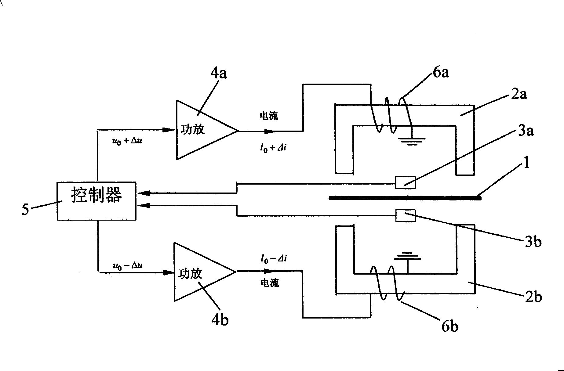
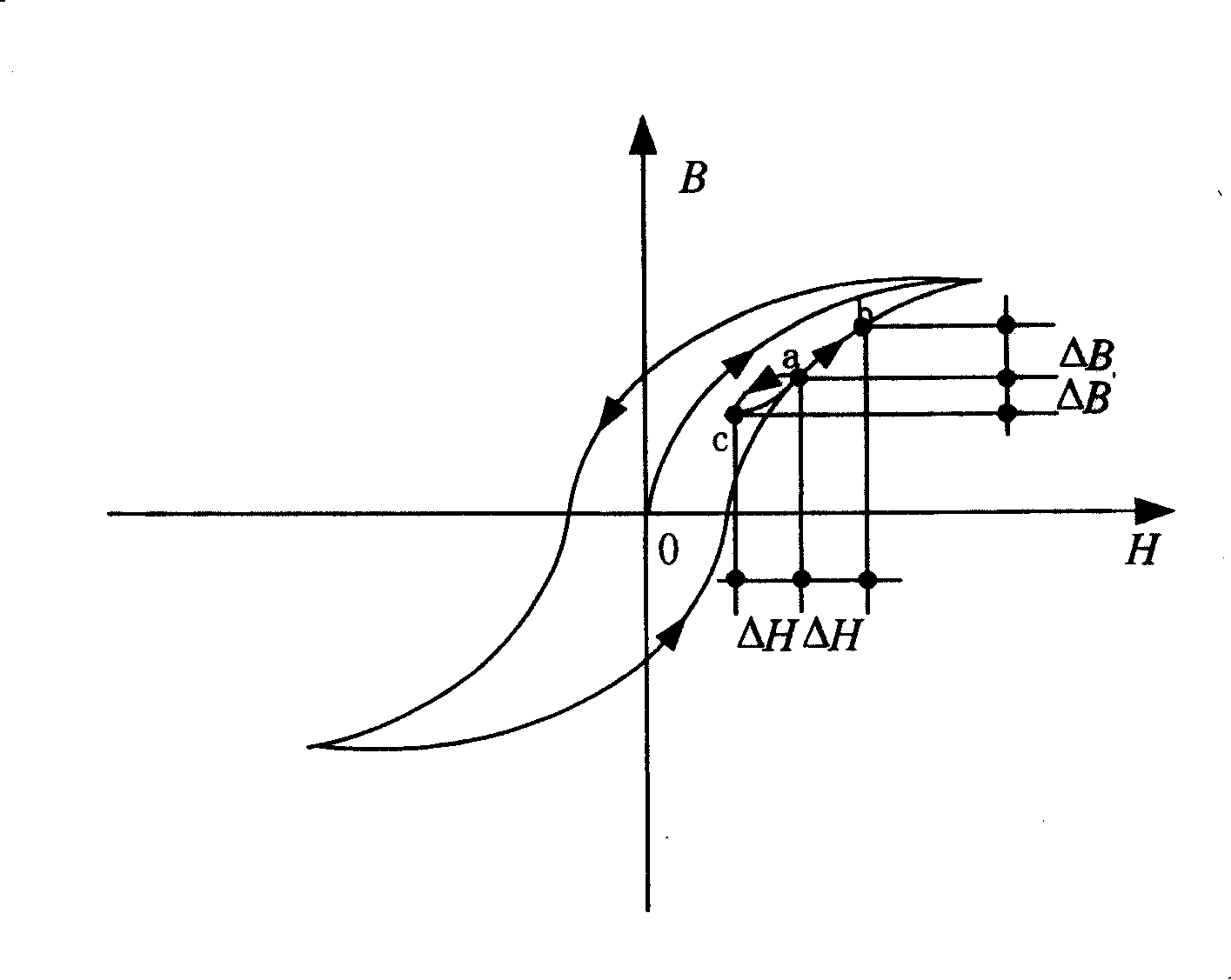
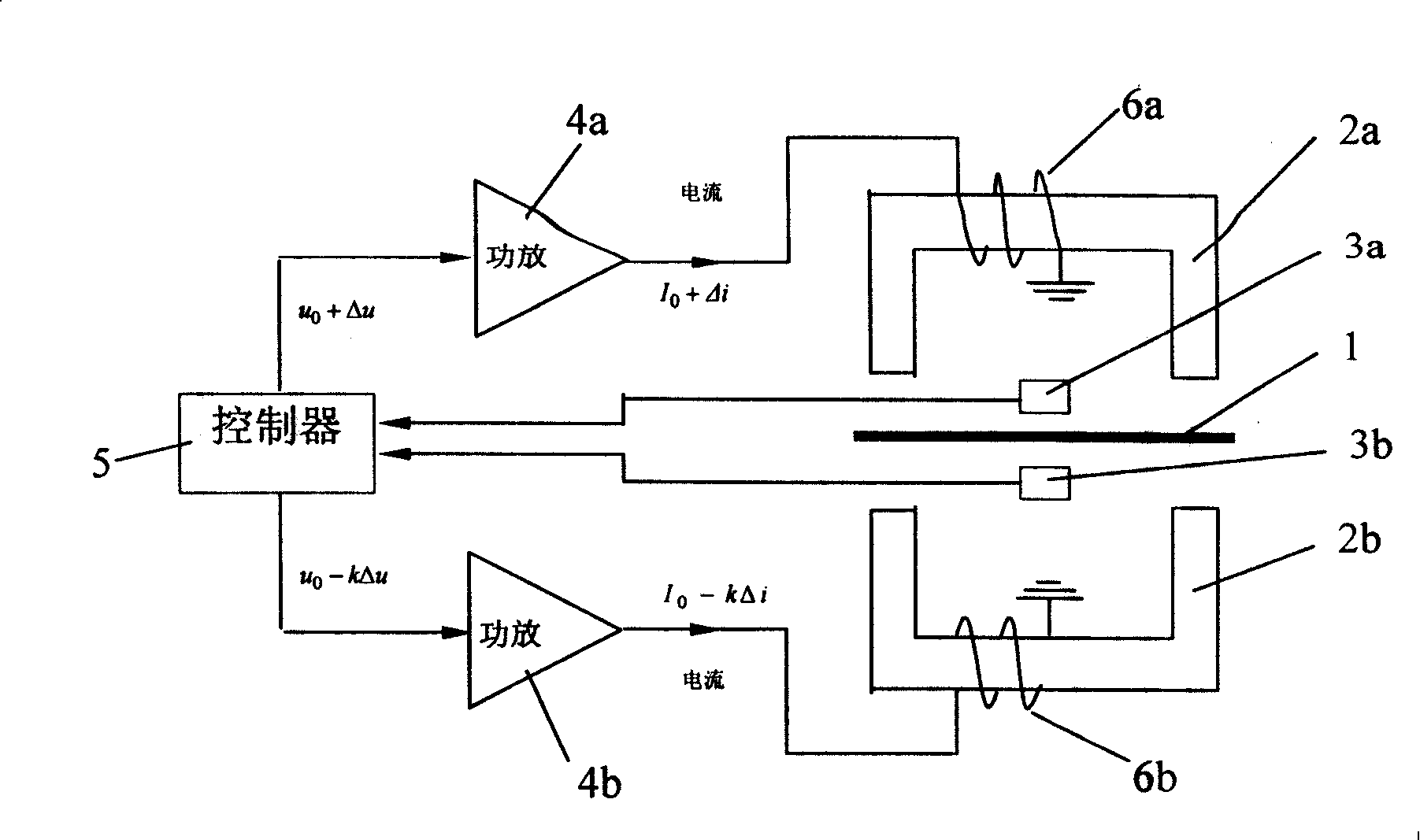
[0048] Please combine image 3 , Figure 4 As shown, when the suspended object 1 deviates from the original equilibrium position under external disturbance, use the sensors 3a and 3b to measure the deviation, and then use the controller 5 to generate a differential control signal (u 0 +Δu) and (u 0 -Δu), from which it is judged that the control signal for demagnetization is (u 0 -Δu), for the control signal (u 0 -Δu) is weighted, multiplied by a weighting factor k to obtain (u 0 -kΔu) control signal, use the power amplifier 4a to control the signal (u 0 +Δu) is converted into the exciting current of coil 6a (I 0 +Δi), use the power amplifier 4b to convert the control signal (u 0 -kΔu) is converted into the exciting current of coil 6b (I 0 -kΔi), please combine with that shown in Figure 5, since the increase Δi of the magnetic induction of the diff...

Embodiment 2

[0050] The method of increasing the compensation current by adding compensation coils and corresponding compensation power amplifiers is the hardware method.

[0051] Please combine with Fig. 6 and Fig. 7, add a compensation coil 7a and a compensation power amplifier 4c corresponding to the compensation coil 7a on the differential electromagnet 2a; Coil 7b correspondingly compensates power amplifier 4d. When the suspended object 1 deviates from the original equilibrium position under external disturbance, use the sensors 3a and 3b to measure the deviation, and then use the controller 5 to generate a differential control signal (u 0 +Δu) and (u 0 -Δu), from which it is judged that the control signal for demagnetization is (u 0 -Δu), the control signal (u 0 +Δu) and (u 0 -Δu) is converted into the excitation current of coils 6a and 6b (I 0 +Δi) and (I 0 -Δi); then use the controller 5 to generate a compensation signal Δu ', use the corresponding compensation power amplifie...


PUM


Abstract

The invention discloses a compensation method for magnetic suspension hysteresis, comprising the following steps of: using a sensor to measure offset; using a controller to generate a differential control signal, and judging a demagnetization control signal; processing weighing treatment for the demagnetization control signal; using a power amplifier to generate excitation current of generating magnetization and demagnetization respectively; wherein, the excitation current enables the increasing amount equal to the decreasing amount of magnetic strength generated by the differential electromagnet; or making the increasing amount equal to the decreasing amount of a magnetic strength generated by the differential electromagnet by increasing the compensation current for increasing compensation coil and corresponding compensation power amplifier. The invention compensates magnetic hysteresis. The invention is simple and convenient, stable and reliable. The invention makes the increasing amount equal to the decreasing amount of magnetic strength generated by the differential electromagnet. The invention carbonizes and equalizes magnetization and demagnetization. The invention guarantees the suspended matter restore to balancing position, so as to improve stability of the magnetic suspension system.

Description

technical field [0001] The invention relates to the electromagnetic force control of the magnetic levitation, and more specifically, relates to a compensation method for the hysteresis of the magnetic levitation. Background technique [0002] Magnetic levitation bearings and magnetic strip stabilization systems work basically the same, see figure 1 As shown, the suspended object 1 will deviate from the original equilibrium position under external disturbance, the deviation is measured by the sensors 3a and 3b, and the controller 5 generates a differential control signal (u 0 +Δu) and (u 0 -Δu), the power amplifiers 4a and 4b convert the control signal into the excitation current of the coil 6a and 6b (I 0 +Δi) and (I 0 -Δi), the excitation current causes the electromagnets 2a and 2b to generate differential magnetic fields respectively, and the suspended object 1 is subjected to the resultant force of the magnetic field in the differential magnetic field, and the directio...

Claims


Application Information

Patent Timeline
IPC IPC(8): H02N15/00
Inventor 陈培林徐龙祥王泽济金超武张永杰
Owner BAOSHAN IRON & STEEL CO LTD
Why Eureka
Try Eureka