Micro powder dry-type magnetic separator

A magnetic separator and dry technology, applied in the field of micropowder dry magnetic separator, can solve the problems of ineffective separation, coarse separation, low separation efficiency, etc., achieve good iron removal effect, and solve separation problems. Difficult, large surface area effect

Inactive Publication Date: 2009-12-09
WUHAN UNIV OF SCI & TECH +1
View PDF0 Cites 19 Cited by
  • Summary
  • Abstract
  • Description
  • Claims
  • Application Information

AI Technical Summary

Problems solved by technology

[0004] The current dry magnetic separator has the following disadvantages: the suitable sorting particle size is relatively coarse, and the sorting force mainly depends on magn

Method used


Image

  • Micro powder dry-type magnetic separator
  • Micro powder dry-type magnetic separator
  • Micro powder dry-type magnetic separator

Examples


Embodiment 1

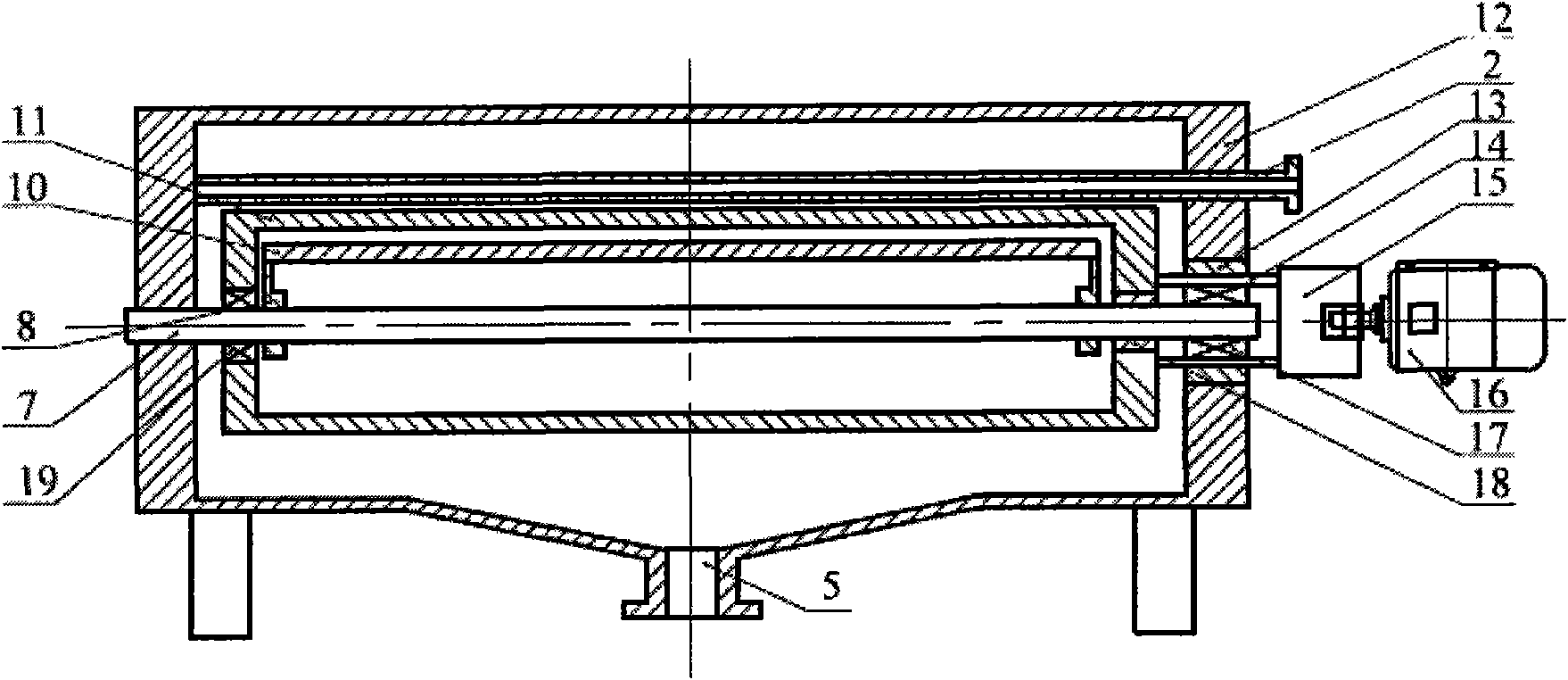
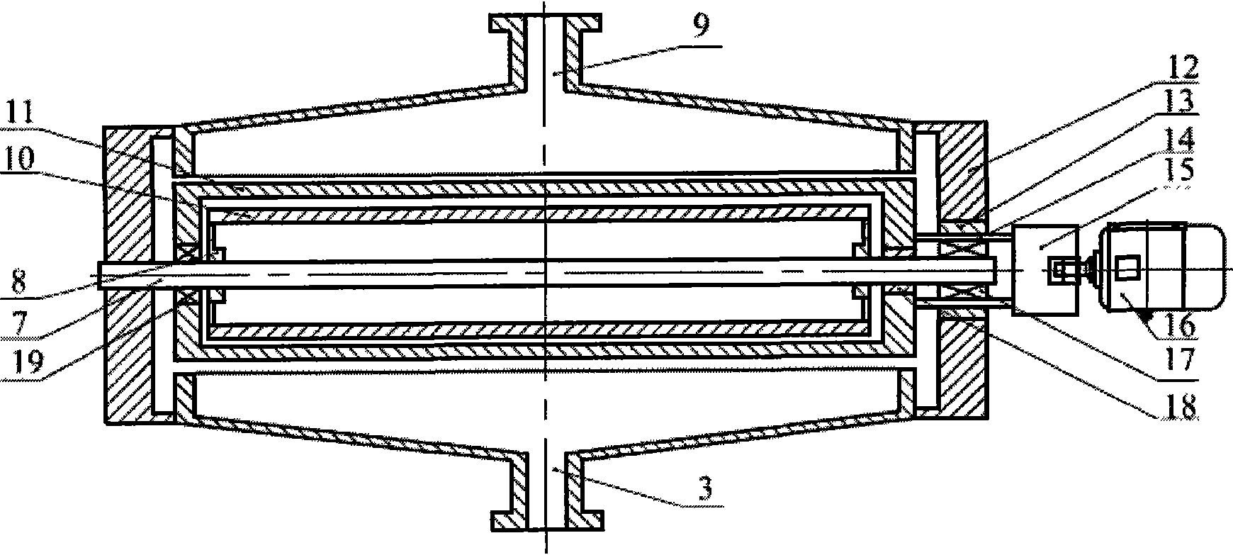
[0021] A kind of micropowder dry type magnetic separator, its structure is as follows figure 2 and image 3 As shown: the two ends of the magnetic drum 11 are respectively concentrically installed on the fixed shaft 7 through the left end bearing 19 and the right end shaft bushing 18, the left end of the fixed shaft 7 is fixed on the left side of the sealed casing 12, and the fixed shaft 7 The right end passes through the shaft bushing 18 and is horizontally installed in the right end bearing 17 in the hollow shaft 14; the right side of the magnetic drum 11 is connected with the hollow shaft 14, the motor 16 is connected with the hollow shaft 14 through the reducer 15, and the hollow shaft 14 passes through The bearing bush 13 is installed on the right side of the sealed casing 12 .

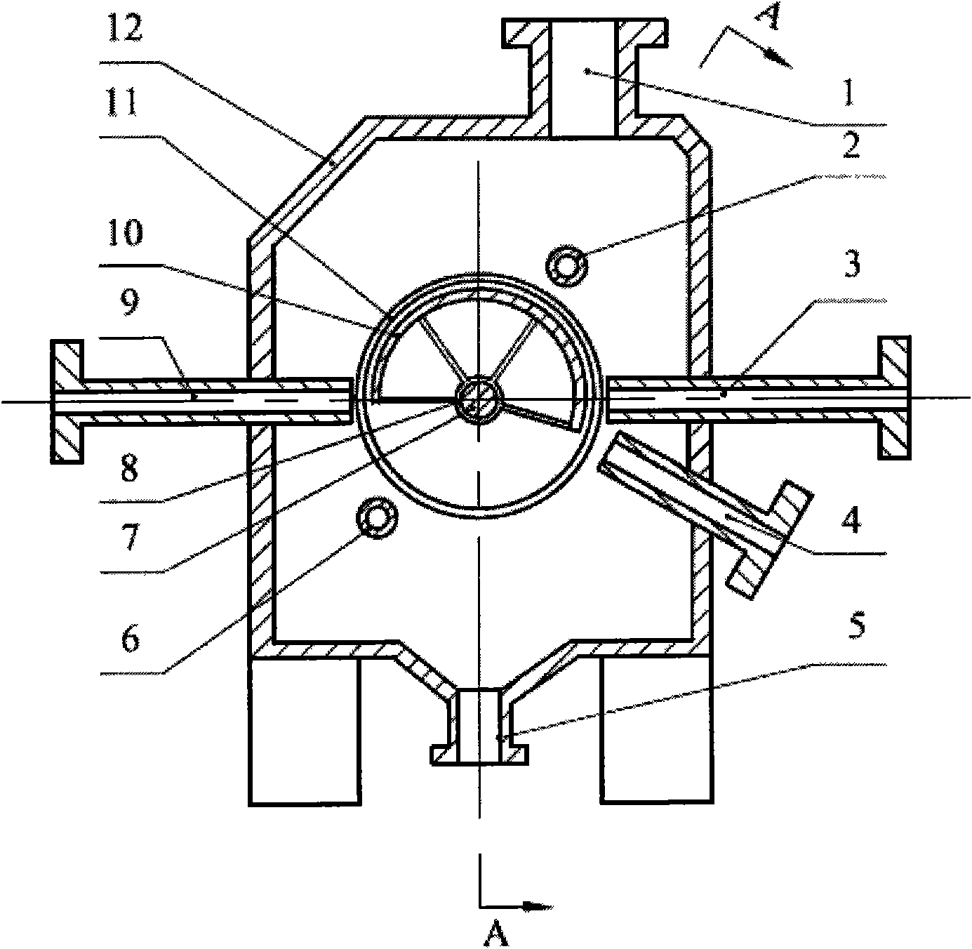
[0022] Such as figure 1 As shown: a magnetic system 10 is installed concentrically in the magnetic drum 11 , the magnetic system 10 is fixedly installed on the fixed shaft 7 through the magnet...

Embodiment 2

[0030] A micropowder dry magnetic separator, two first air ducts 2 and second air ducts 6 are installed horizontally on the upper right and lower left of the magnetic drum 11 along the axial direction of the magnetic drum 11 respectively.

[0031] Magnetic system 10 such as figure 1 As shown, the gap between the outer arc surface and the inner wall of the magnetic drum 11 is 8-10mm, the wrap angle of the magnetic system 10 is 210-220°, and the gap between the end faces on both sides of the magnetic system and the inner wall on both sides of the magnetic drum is 15-20mm.

[0032] The gap between the outer wall of the first air duct 2 and the second air duct 6 and the outer wall of the magnetic drum 11 is 10-15 mm, and the inner diameter of the first air duct 2 and the second air duct 6 is 45-50 mm; The air outlet holes of the air duct 6 have a diameter of 2 to 3 mm, and the center distance of the air outlet holes is 5 to 6 mm.

[0033] The angle between the center line of the ...


PUM


Abstract

The invention relates to a micro powder dry-type magnetic separator; the technical proposal is that: the two ends of a magnetic rotary drum (11) are respectively arranged on a fixing shaft (7) concentrically by a left end bearing (19) and a right end shaft liner (18), the right side of the magnetic rotary drum (11) is connected with a hollow shaft (14), a motor (16) is connected with the hollow shaft (14) by a speed reducer (15), a magnetic system (10) is concentrically arranged in the magnetic rotary drum (11), the upper right part and the bottom left part of the magnetic rotary drum (11) are respectively provided with one to two first air duct (2) and a second air duct (6) along the axial direction, a row of air outlet holes are uniformly opened on the first air duct (2) and the second air duct (6) towards to one side of the magnetic rotary drum (11), a sealing type machine shell (12) above the magnetic rotary drum (11) is provided with a tailings outlet (1), the sealing type machine shell (12) at the left side of the magnetic rotary drum (11) is provided with a first middling outlet (9), and the sealing type machine shell (12) at the bottom right part of the magnetic rotary drum (11) is provided with a second middling outlet (4). The micro powder dry-type magnetic separator has the characteristics of high separating purity of high recovery rate of magnetic products.

Description

technical field [0001] The invention belongs to the technical field of dry magnetic separators. In particular, it relates to a micropowder dry magnetic separator. Background technique [0002] The rapid development of the steel industry has accelerated the demand for iron ore. my country's iron ore resources have the characteristics of "poor, fine, and miscellaneous", and most of them are located in remote areas with drought and little rain, so wet sorting is almost impossible. Mineral embedding is fine in particle size, so it goes without saying that it consumes a lot of grinding costs. Under the premise of wet fine grinding and classification, a large number of fine particles are produced, and the specific surface area of ​​the particles increases greatly, which makes it difficult to dehydrate the products after wet separation, and the moisture content of magnetic products is relatively high. A high moisture content will inevitably increase additional drying operations,...

Claims


Application Information

Patent Timeline
IPC IPC(8): B03C1/12C22B1/02C04B7/36
CPCY02P10/20
Inventor 杨大兵吴明张毅刘抗强
Owner WUHAN UNIV OF SCI & TECH
Why Eureka
Try Eureka