
Numerical control groove cut-off apparatus

A bevel cutting and cutting torch technology, applied in the field of CNC bevel cutting devices, can solve the problems of many mechanical rods, large movement space, and easy damage, and achieve the effects of saving production costs and reducing the volume of the mechanism

Inactive Publication Date: 2008-08-20
上海气焊机厂有限公司
View PDF0 Cites 5 Cited by
  • Summary
  • Abstract
  • Description
  • Claims
  • Application Information

AI Technical Summary

Problems solved by technology

[0003] The technical problem to be solved by the present invention is to provide a numerically controlled bevel cutting device to overcome the defects of the prior art with many mechanical rods (systems), large movement space and easy damage

Method used


Image

  • Numerical control groove cut-off apparatus
  • Numerical control groove cut-off apparatus
  • Numerical control groove cut-off apparatus

Examples


Embodiment Construction

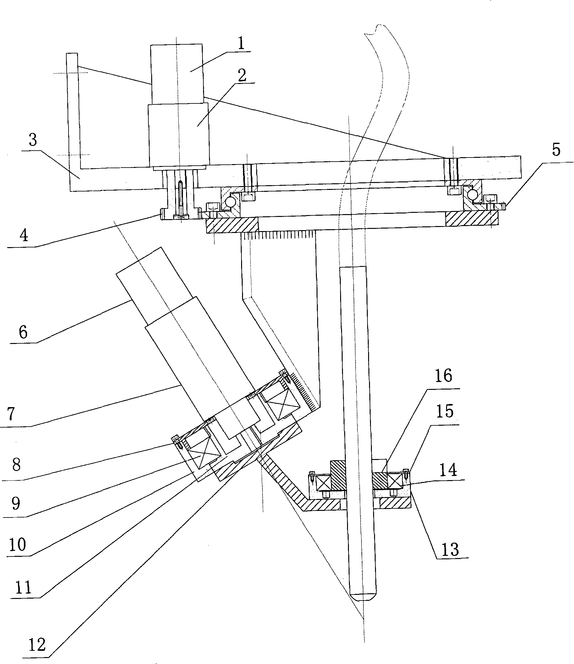
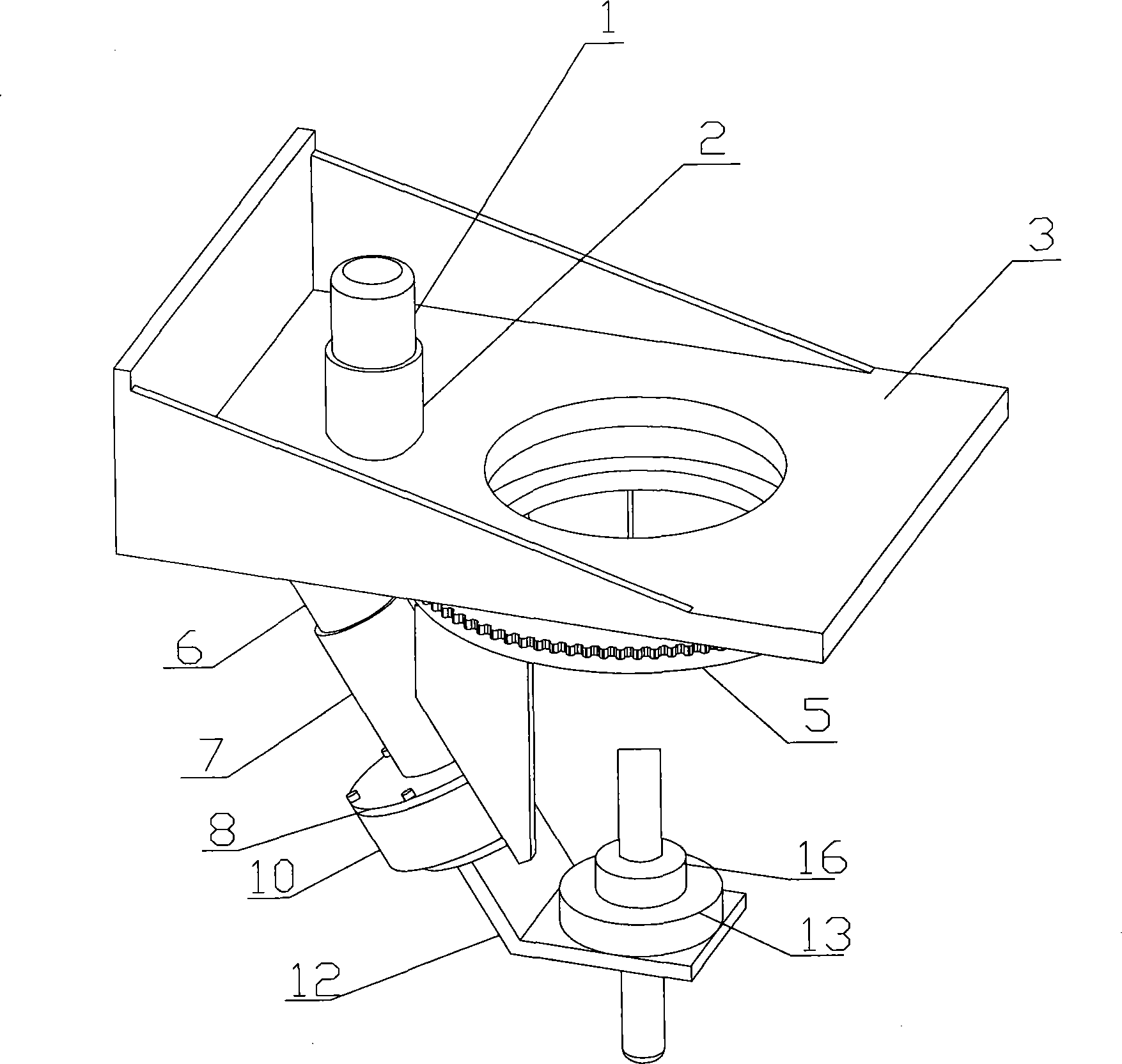
[0014] Such as figure 1 As shown, the bevel cutting device of the present invention is composed of a base 3, a main drive, an auxiliary drive, a torch holder and an external tooth flange bearing 5.

[0015] Among them, the main drive is composed of motor 1, reducer 2 and gear 4. After the motor 1 and the reducer 2 are combined, the pinion 4 is set on the extended shaft end of the reducer. Adjust the center distance between the pinion 4 and the external tooth flange bearing 5, and fix the outer rings of the reducer 2 and the external tooth flange bearing 5 on the base 3 respectively after meshing correctly.

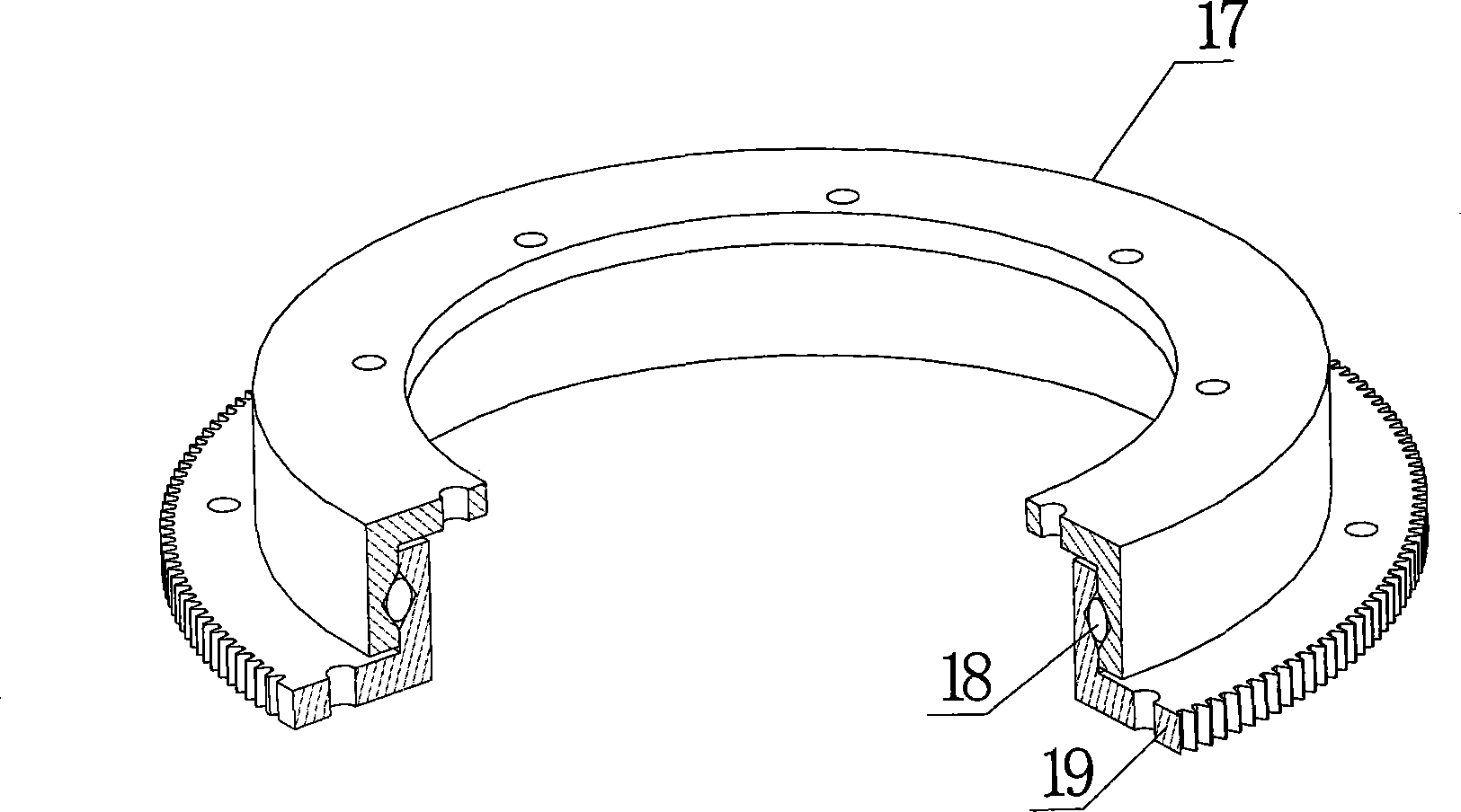
[0016] Such as figure 1 , figure 2 and Figure 4 , Auxiliary drive is made up of motor 6, speed reducer 7, rotating body 10, bearing 9, end bearing cover 8, coupling 11 and angle rotating shaft 12. After the motor 6, the reducer 7 and the shaft coupling 11 are connected and combined, the reducer 7 and the bearing end cover 8 are fixed on the rotating body 10 in seque...


PUM


Abstract

The invention discloses a numerical control groove cutting device of multilateral curve type parts, comprising major-minor driving pieces and a clamping piece, which is characterized in that the major-minor driving pieces are connected by an external tooth flange bearing (5), and the outer race of the external tooth flange bearing is fixed on the base (3), an external tooth which is meshed with the major driving piece is arranged outside the flange of the inner ring, and the inner ring and the minor driving piece are fixedly connected. The numerical control groove cutting device has the advantages that the prior space parallel four-bar mechanism and the external tooth or fan tooth meshed mechanism is promoted to a structure of fixed rotation and angle rotating shaft deflection, not only the cost of the research and development is saved, but also the mechanism volume is greatly reduced, so that all-in-one of the rotation, the connection, and the serrated meshing is achieved.

Description

technical field [0001] The invention belongs to the cutting technology, in particular to a numerically controlled bevel cutting device capable of completing polygonal curve parts. Background technique [0002] Cutting is an important process in welding production. Before welding, it is usually necessary to make a bevel on the welded joint of the steel plate. The traditional groove processing mostly adopts portal cutting machine plus CNC milling or manual cutting, and completes the cutting of groove parts after cold (gold) processing. Although the portal cutting machine has the characteristics of high cutting precision and high efficiency, it cannot realize the spatial swing of the cutting torch axis and complete the bevel cutting of polygonal curve parts. The newly commercially available CNC portal cutting machine has improved performance, the axis of the cutting torch can swing in space, and can cut the bevel of polygonal curve parts. Its technology is based on the princi...

Claims


Application Information

Patent Timeline
IPC IPC(8): B23K37/00B23K37/02B23Q5/00
Inventor 丁书才闫海永
Owner 上海气焊机厂有限公司
Learn More