Sanding system of container soldering joint

A container and sand technology, applied in abrasive feeding devices, abrasives, metal processing equipment, etc., can solve the problems of harsh operating environment for workers, unstable system air pressure, high operating costs, and improve workers’ working conditions and energy utilization. The effect of improving the rate and stable sand quality

Inactive Publication Date: 2008-08-20
CHINA INTERNATIONAL MARINE CONTAINERS (GROUP) CO LTD +1
View PDF0 Cites 5 Cited by
  • Summary
  • Abstract
  • Description
  • Claims
  • Application Information

AI Technical Summary

Problems solved by technology

[0003] 1. The existing pneumatic sandblasting system for container welds converts electrical energy into air pressure energy through the air compressor and stores it in the compressed air. The compressed air is transported to the pneumatic sandblasting machine through the pipeline. The air pressure can be converted into the mechanical energy of the sand material to polish and clean the surface of the weld seam of the box; at the same time, the pneumatic sandblasting system of the container weld seam needs to lay a long pipeline system for the transmission of compressed air, and the air pressure of the compressed air can be transmitted in the compressed air. Big loss in the process
Therefore, the welding seam pneumatic sand blasting system converts the energy twice, and in the process of energy conversion and transmission, the energy utilization efficiency is low, resulting in a great waste of energy;
[0004] 2. The pneumatic sand blasting system for container welds requires manual operation of the sand gun, the system air pressure is unstable, and its sand blasting quality is affected by manual factors and system air pressure fluctuations;
[0005] 3. The operating environment of workers is harsh;
[0006] 4. The pneumatic sandblasting system for container welds requires a large investment and high operating costs

Method used


Image

  • Sanding system of container soldering joint
  • Sanding system of container soldering joint
  • Sanding system of container soldering joint

Examples


Embodiment Construction

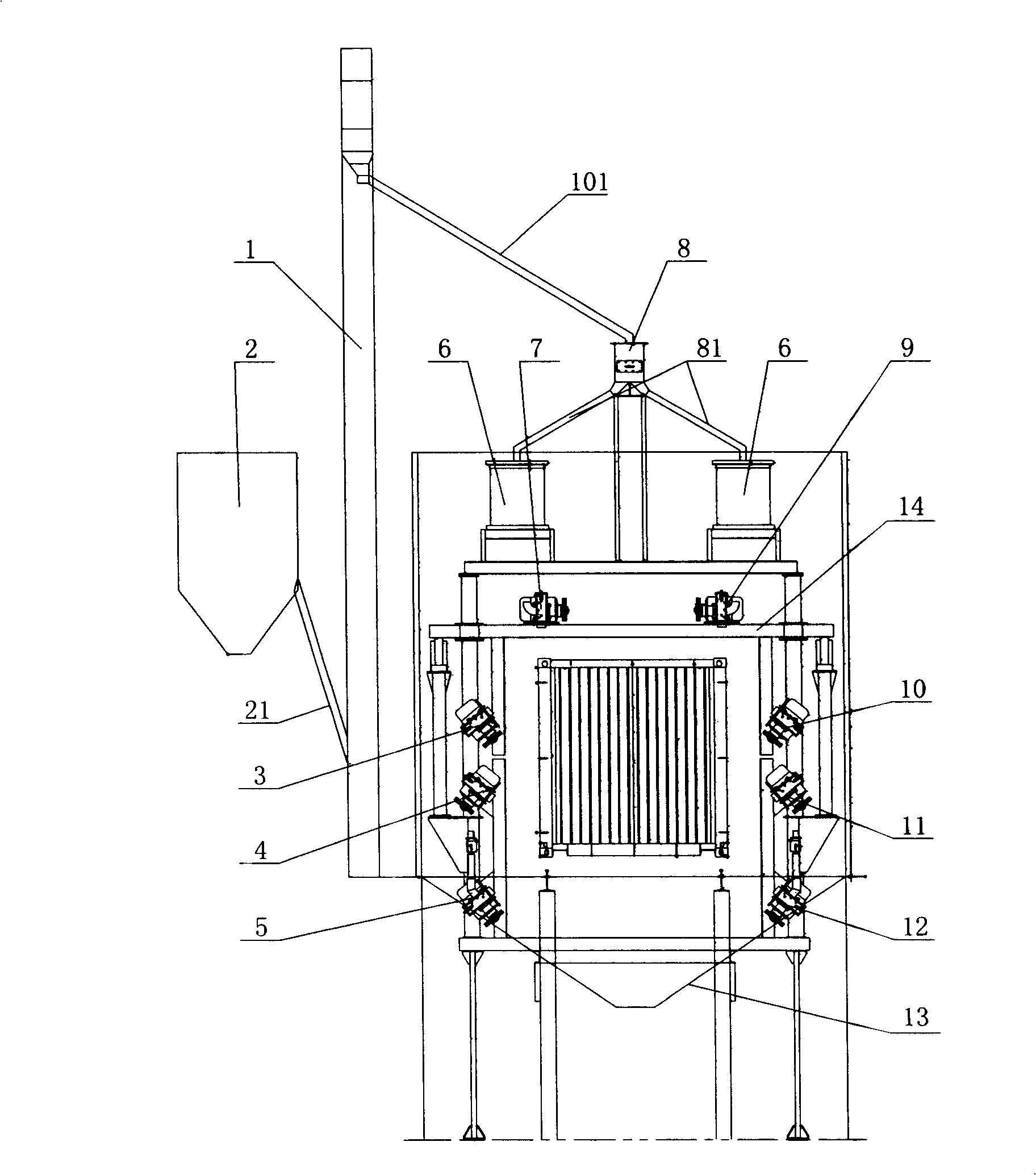
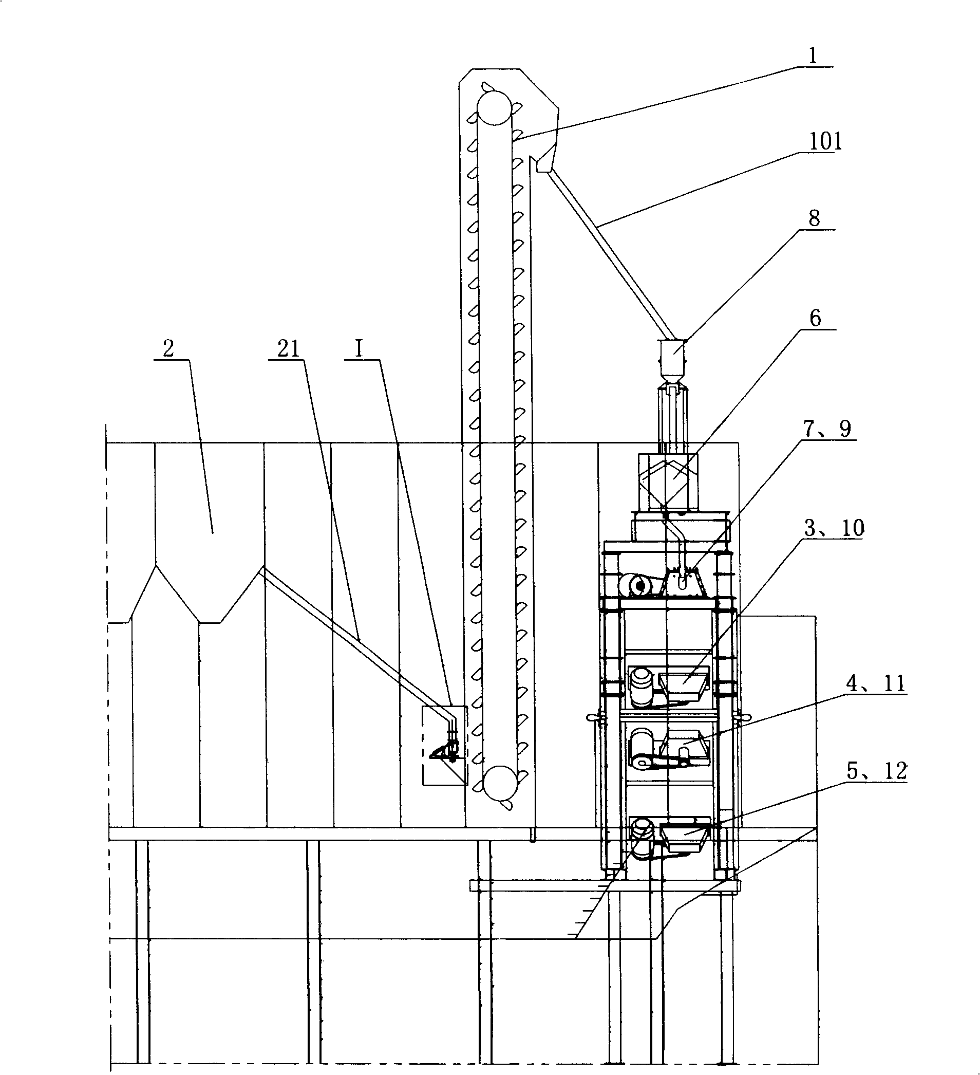
[0025] figure 1 , 2 An embodiment of the container weld seam blasting system of the present invention is shown. Such as figure 1 , figure 2 As shown, the container welding seam blasting system includes a sand conveying section, a sand separating section and a sand blasting section connected in sequence. The sand blasting section includes a door-shaped frame 14 arranged on the container conveying line, electric shot blasting machines 3, 4, 5 and 10, 11, 12 arranged on the structures on both sides of the door-shaped frame 14, and The electric shot blasting machines 7 and 9 on the upper structure, among them, the electric shot blasting machines 7 and 9 process the two welds on both sides of the container top plate and the container top side beam respectively, and the electric shot blasting machines 3, 4, 5 and the electric shot blasting machines Shot blasting machines 10, 11, and 12 respectively process the two welds between the side plate and the top side beam of the contai...


PUM


Abstract

The invention relates to a welding line sanding system for containers, which comprises a sand conveying workshop section, a sand separating workshop section, and a sanding workshop section which are all connected in sequence; wherein, the sanding workshop section comprises a door-shaped frame arranged on a container conveyor line for allowing the containers to pass through, and a plurality of electric shot-blasting devices arranged on the two sides and upper part of the door-shaped frame; the electric shot-blasting devices are arranged according to the container welding lines to be cleared, and the sand slinging openings of the electric shot-blasting devices are facing towards the container welding line to be cleared. The sand separating workshop section comprises a distribution bin, a distribution device for connecting the distribution bin and the electric shot-blasting devices; the distribution bin and the distribution device distribute the stored sands by use of potential energy, and the sand conveyor workshop section conveys the sand into the distribution bin. The welding line sanding system in the invention has the advantages of enhancing the energy utilization rate, realizing the fully mechanized sanding, getting rid of manual operations, improving the working environment for workers, stabilizing and further bettering the sanding quality compared with the pneumatic sand blasting system, and reducing the investment and operation costs compared with the pneumatic sand blasting system.

Description

technical field [0001] The invention relates to a container production weld seam cleaning system, in particular to a container weld seam blasting system. Background technique [0002] The existing container production line has always used a pneumatic sandblasting system for surface treatment of the top plate welds and side plate welds of the box body. The existing pneumatic sandblasting system for container welds has the following defects: [0003] 1. The existing pneumatic sandblasting system for container welds converts electrical energy into air pressure energy through the air compressor and stores it in the compressed air. The compressed air is transported to the pneumatic sandblasting machine through the pipeline. The air pressure can be converted into the mechanical energy of the sand material to polish and clean the surface of the weld seam of the box; at the same time, the pneumatic sandblasting system of the container weld seam needs to lay a long pipeline system fo...

Claims


Application Information

Patent Timeline
Patent Type & Authority Applications(China)
IPC IPC(8): B24C3/14B24C3/02B24C7/00
Inventor 张新叶正剑赵声录
Owner CHINA INTERNATIONAL MARINE CONTAINERS (GROUP) CO LTD
Why Eureka
Try Eureka