
Energy-saving emission-reducing air port

A technology for energy saving, emission reduction, and airports, which is applied to aircraft parts, aircraft ground control, and ground devices to achieve the effects of saving flight energy consumption, shortening take-off time, and reducing take-off fuel.

Inactive Publication Date: 2010-06-30
黄金伦
View PDF2 Cites 0 Cited by
  • Summary
  • Abstract
  • Description
  • Claims
  • Application Information

AI Technical Summary

Problems solved by technology

[0002] Prior art aircraft take-off: first use high power and large sewage to form aerodynamic performance conditions, and then indirectly improve the aircraft take-off, so there must be a long runway, aircraft landing gear and a hydraulic system for retracting and retracting the landing gear

Method used


Image

  • Energy-saving emission-reducing air port
  • Energy-saving emission-reducing air port
  • Energy-saving emission-reducing air port

Examples


Embodiment Construction

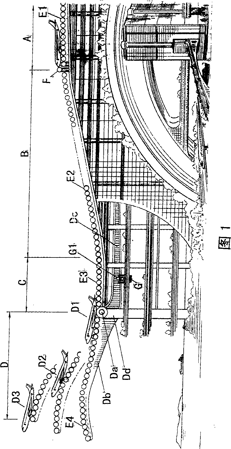
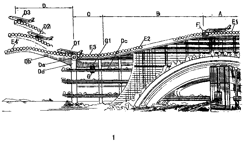
[0008] see figure 1 , Section A is the passenger boarding apron (the top should be covered with the roof of the photovoltaic power generation system, not shown), the aircraft is parked on the slightly lower slope of the nose, and the nose is raised and blocked by two lifting rollers F.

[0009] When the aircraft takes off, the airport command center lowers the lifting roller F and starts the power roller E1 (many linkages). Make the plane slide smoothly into the slope and lie down. The hundreds of tons of the plane are full of acceleration power rollers with digital frequency conversion technology, so the plane will be rolled downhill by the roller system at a very fast speed, and the acceleration is getting bigger and bigger. When the plane is about to approach the end of slope B, the sensor there will send a signal to the display screen of the driving instrument to start the engine easily along the potential energy; the plane rushes over C quickly with the huge inertia and t...


PUM


Abstract

The invention discloses an energy-saving and emission reduction airport (1), comprising an A section micro slope apron, a B section slope power driving roller, and a C section horizontal power driving roller. The multilayer building of the airport, bases of A, B, C section power driving rollers, is fixed while the D section is a rocker arm Db lifting power driving roller seat with Da as the pivot. All the power driving rollers E1, E2, E3 and E4 are provided with sensors, which can give in-time feedback to the airport computer before commanding E1, E2, E3 and E4 to power on (off) at a proper time to drive speeding up (digital frequency and speed conversion) roller to drive the airplane accelerating and control the rocker arm Db lifting the airplane climbing high in a short cut. The technical proposal has the advantages that the clean energy combining with the energy storing equipment replaces the prior art of the high power energy consumption centralized emission, improving the takeoffand passing by efficiency and reducing the occupied area.

Description

technical field [0001] The invention relates to an energy-saving and emission-reducing scheme for an airport when an airplane takes off, and is an energy-saving and emission-reducing airport. Background technique [0002] Aircraft take-off in the prior art: first use high power and large sewage to form aerodynamic performance conditions, and then indirectly improve the aircraft to take off, so there must be a long runway, aircraft landing gear and a hydraulic system for retracting the landing gear. Contents of the invention [0003] Purpose of the invention: (a) save the landing gear and the long runway of the aircraft; (b) use the scheme of high-efficiency roller transmission to increase the speed of the aircraft to take off, replace the indirect formation of aerodynamic performance conditions with large power consumption, and then increase the speed of the aircraft to slowly roll and take off conventional. [0004] The technical scheme of the present invention: includin...

Claims


Application Information

Patent Timeline
Patent Type & Authority Patents(China)
IPC IPC(8): B64F1/36G08G5/06
Inventor 黄金伦
Owner 黄金伦
Learn More