Switching valve

A technology for switching valves and valve seats, which is applied in the direction of sliding valves, valve devices, engine components, etc., and can solve problems such as water leakage, short service life, and poor matching precision

CN101245862AInactive Publication Date: 2008-08-20WEN SHENG FU CO LTD
0 Cites 0 Cited by

Patent Information

Authority / Receiving Office
CN · China
Patent Type
Applications(China)
Current Assignee / Owner
Publication Date
2008-08-20
Estimated Expiration
Not applicable · inactive patent

Smart Images

  • Figure 1
    Figure 1
  • Figure 2
    Figure 2
  • Figure 3
    Figure 3
Patent Text Reader

Abstract

The invention provides a shifting valve, comprising a valve seat, a precise ceramic control valve, a locking cover and a hand group; wherein, the valve seat is internally provided with a receiving trough. The whole circumference of the receiving trough is provided with the locking section of a thread. A water inlet passage is arranged below the receiving trough and a water outlet passage is arranged at one side of the external side of the receiving trough. The precise ceramic control valve is controlled internally by precise ceramic sheets. An internal locking section is arranged above the precise ceramic control valve; a water inlet hole is arranged below the precise ceramic control valve and a water outlet hole is arranged at the side edge of the precise ceramic control valve. A control rod extends above the precise ceramic control valve and controls the actions of the ceramic sheet group. A locking cover is locked and covered outside the receiving trough. The control rod extends out of a prearranged perforation. The handle group is combined on the control rod. With the structures, the shifting valve which has better assembly structure, longer service life and is not easy to generate water leakage phenomenon is formed.
Need to check novelty before this filing date? Find Prior Art

Description

technical field

[0001] The invention relates to a "switching valve" installed between the water outlet equipment and the water inlet pipeline, or in the middle section of the water inlet pipeline, for cutting and controlling the water inlet and outlet of the water inlet pipeline. When water leakage occurs in the back section of the road, the water source can be closed to facilitate maintenance. Background technique

[0002] In its buildings, a main water pipe is used to connect several auxiliary water pipes to extend to various places, and various water equipment such as toilets, washbasins, bathtubs or urinals are installed to use water pipes to provide water sources for water equipment. The use of the switching valve can close the water source circulation of the water pipe when the water equipment is damaged, and the water source end of the water equipment is temporarily cut off for maintenance.

[0003] While the current switching valve, such as Figure 5 As shown, they ...

Examples

Embodiment Construction

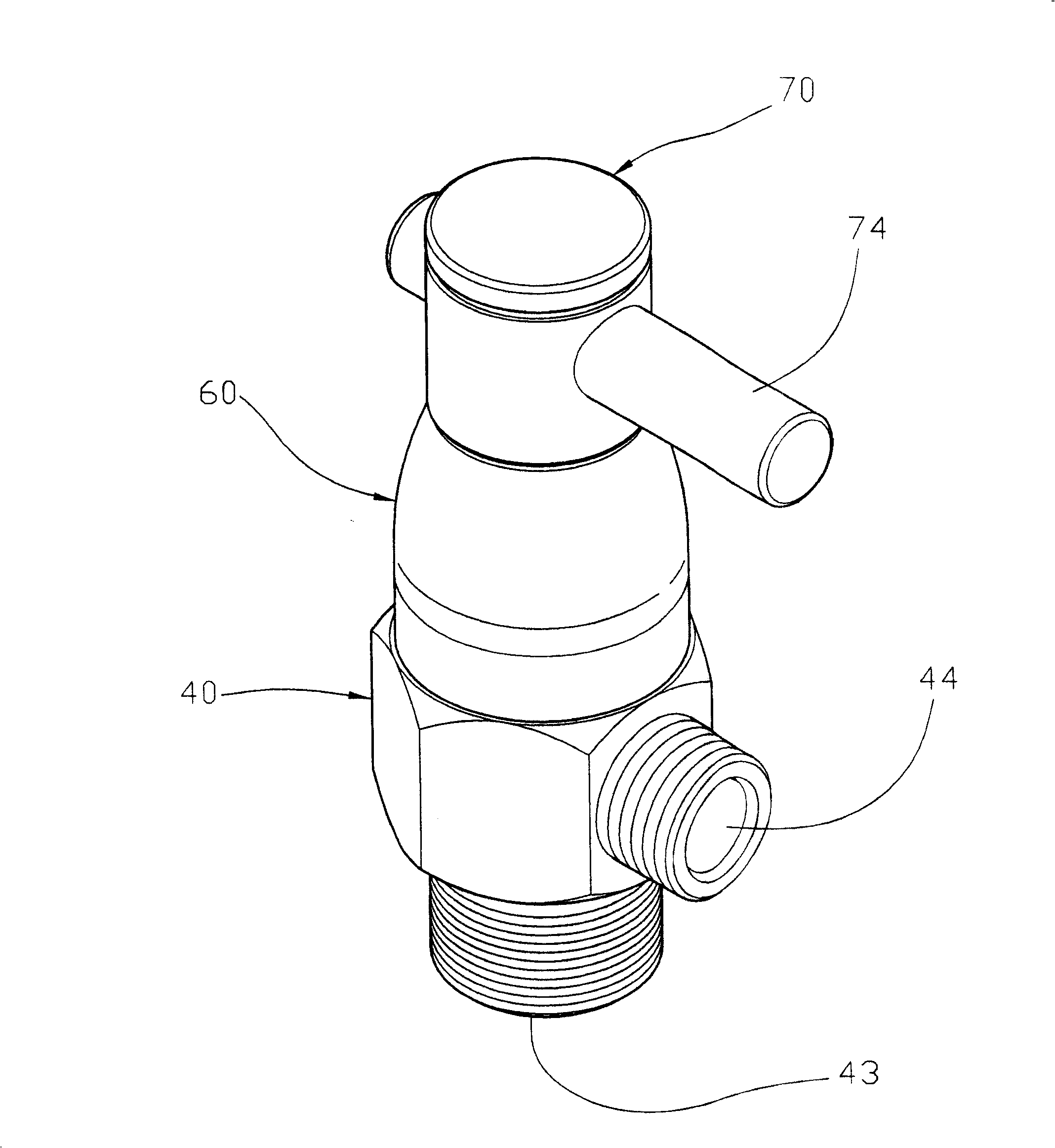
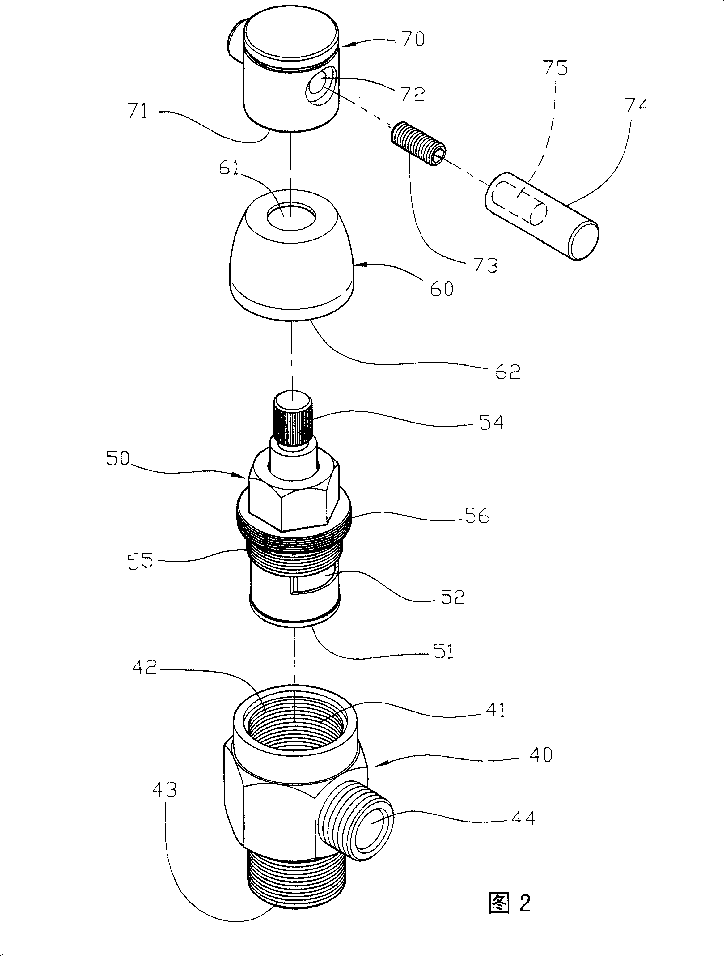
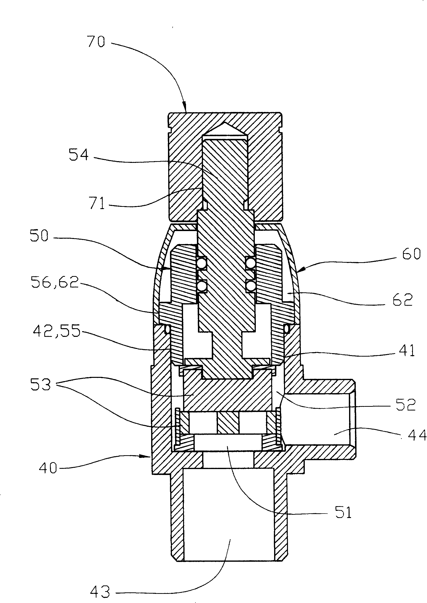
[0026] First of all, please start by figure 1 ,figure 2, image 3 , Figure 4 As shown, it includes: a valve seat 40, a precision ceramic control valve 50, a locking cover 60 and a handle set 70, wherein the valve seat 40 is provided with an accommodating tank chamber 41, the accommodating tank chamber 41 The entire periphery of the body is provided with a threaded locking section 42, and the bottom of the accommodating tank chamber 41 is provided with a water inlet 43, and the outer side is provided with a water outlet 44. The precision ceramic control valve 50 is controlled by a precision ceramic sheet inside. , the bottom is provided with a water inlet 51 and a water outlet 52 is provided on the side. The gap between the water inlet 51 and the water outlet 52 is through a ceramic sheet group 53, and a control rod 54 is extended above the precision ceramic control valve 50. The control The rod 54 is used to control the action of the ceramic disc group 53. In addition, the...