A low-resistance electric thread twister
A low-resistance, electric technology, applied in the direction of metal processing equipment, metal processing, manufacturing tools, etc., can solve the problems of high frictional resistance and achieve the effect of reducing frictional resistance, reducing contact area and reducing wear loss
- Summary
- Abstract
- Description
- Claims
- Application Information
AI Technical Summary
Problems solved by technology
Method used
Image
Examples
Embodiment 1
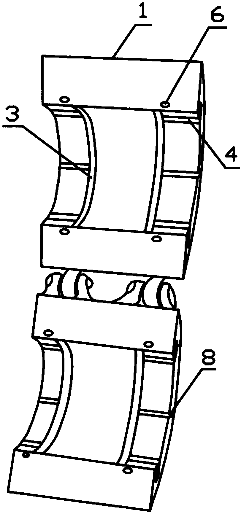
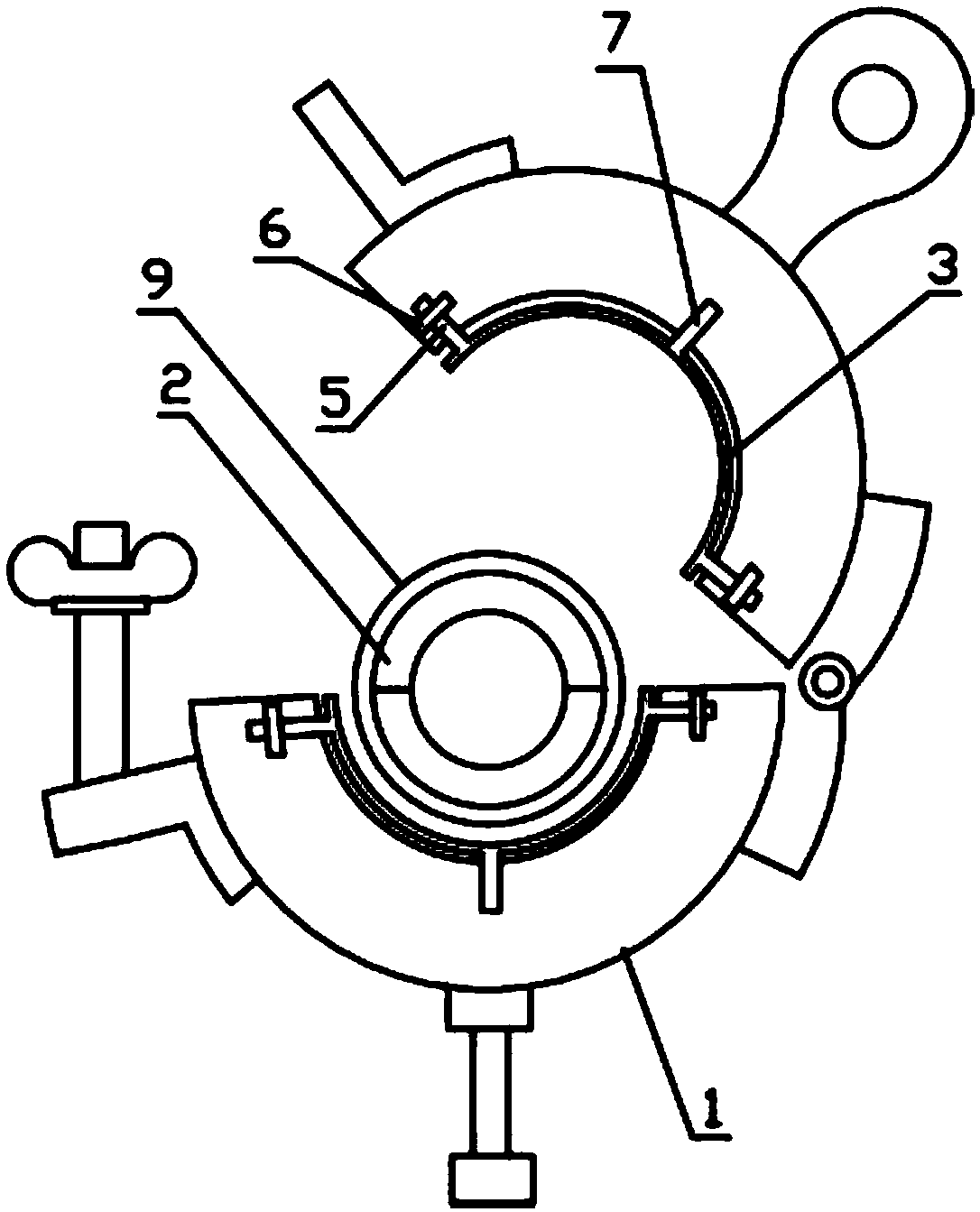
[0023] Such as figure 1 As shown, a low-resistance electric screwing machine of the present invention includes a quick-opening and closing fixing sleeve 1 and a quick-opening and closing clamp 2, and the quick-opening and closing fixing sleeve 1 and the quick-opening and closing clamp 2 are composed of two semi-circular columns It is composed of hinged connection, and the inner wall of each semi-circular column of the quick-opening and closing fixing sleeve 1 is protruded with two semi-circular friction ribs 3, and when the quick-opening and closing fixing sleeve 1 is in a closed state, the four semi-circular friction ribs 3 The friction ribs 3 just constitute two complete friction ribs 3 that surround the inner wall of the fast opening and closing fixing sleeve 1 in the circumferential direction, and the friction ribs 3 are integrally arranged on the inner wall of the quick opening and closing fixing sleeve 1 by welding.
Embodiment 2
[0025] Such as figure 1 and figure 2 As shown, further improvement on the basis of Example 1, the present invention provides a low-resistance electric threading machine, the two ends of the radial opening of the semi-circular column of the quick-opening and closing fixing sleeve 1 are respectively provided with two second A chute 4, the two first chute 4 are located on a straight line in the axial direction of the semicircular column, the long axis extension direction of the first chute 4 is parallel to the axial direction of the semicircular column, and The length of the major axis of the first sliding groove 4 is less than half of the length of the semicircular column; the radial ends of the friction ribs 3 are provided with sliders 5 matching the first sliding groove 4 . The two ends of the radial opening of the semi-circular column are provided with threaded holes vertically interlaced with the first chute 4 . The friction rib 3 moves along the first chute 4 through the...
Embodiment 3
[0028] Further improvement on the basis of Example 2, the present invention provides a low-resistance electric threading machine, the outer wall of the quick opening and closing fixture 2 is protruded along the circumferential direction with two rings of friction rings that match the friction ribs 3 Groove 9.
PUM
 Abstract
Description
Claims
Application Information
 - R&D
- Intellectual Property
- Life Sciences
- Materials
- Tech Scout
- Unparalleled Data Quality
- Higher Quality Content
- 60% Fewer Hallucinations
Browse by: Latest US Patents, China's latest patents, Technical Efficacy Thesaurus, Application Domain, Technology Topic, Popular Technical Reports.
© 2025 PatSnap. All rights reserved.Legal|Privacy policy|Modern Slavery Act Transparency Statement|Sitemap|About US| Contact US: help@patsnap.com


