Image forming apparatus and image forming method
An image and image density technology, applied in the direction of electric recording process applying charge pattern, electric recording process applying electric charge pattern, equipment of electric recording process applying electric charge pattern, etc., can solve the problem of inability to suppress toner scattering, etc., Achieve long-term stable image quality and suppress toner scattering
- Summary
- Abstract
- Description
- Claims
- Application Information
AI Technical Summary
Problems solved by technology
Method used
Image

Examples
no. 1 approach
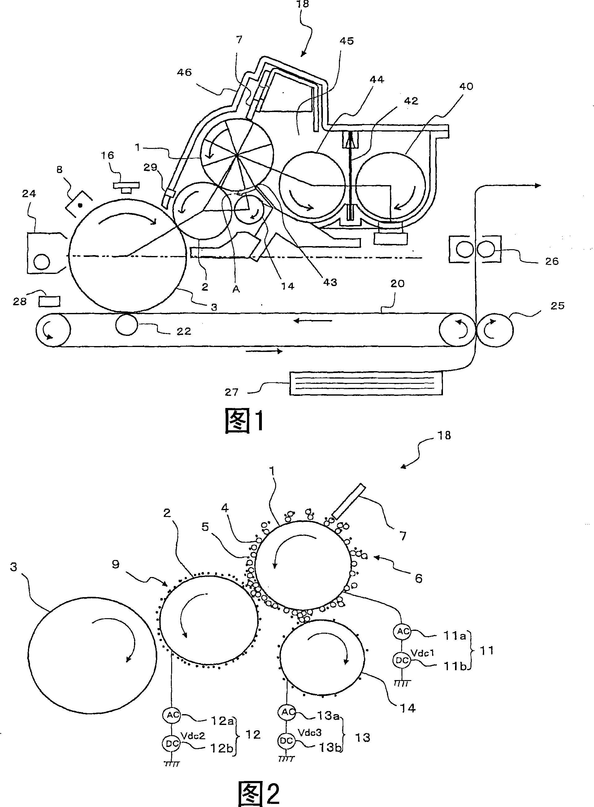
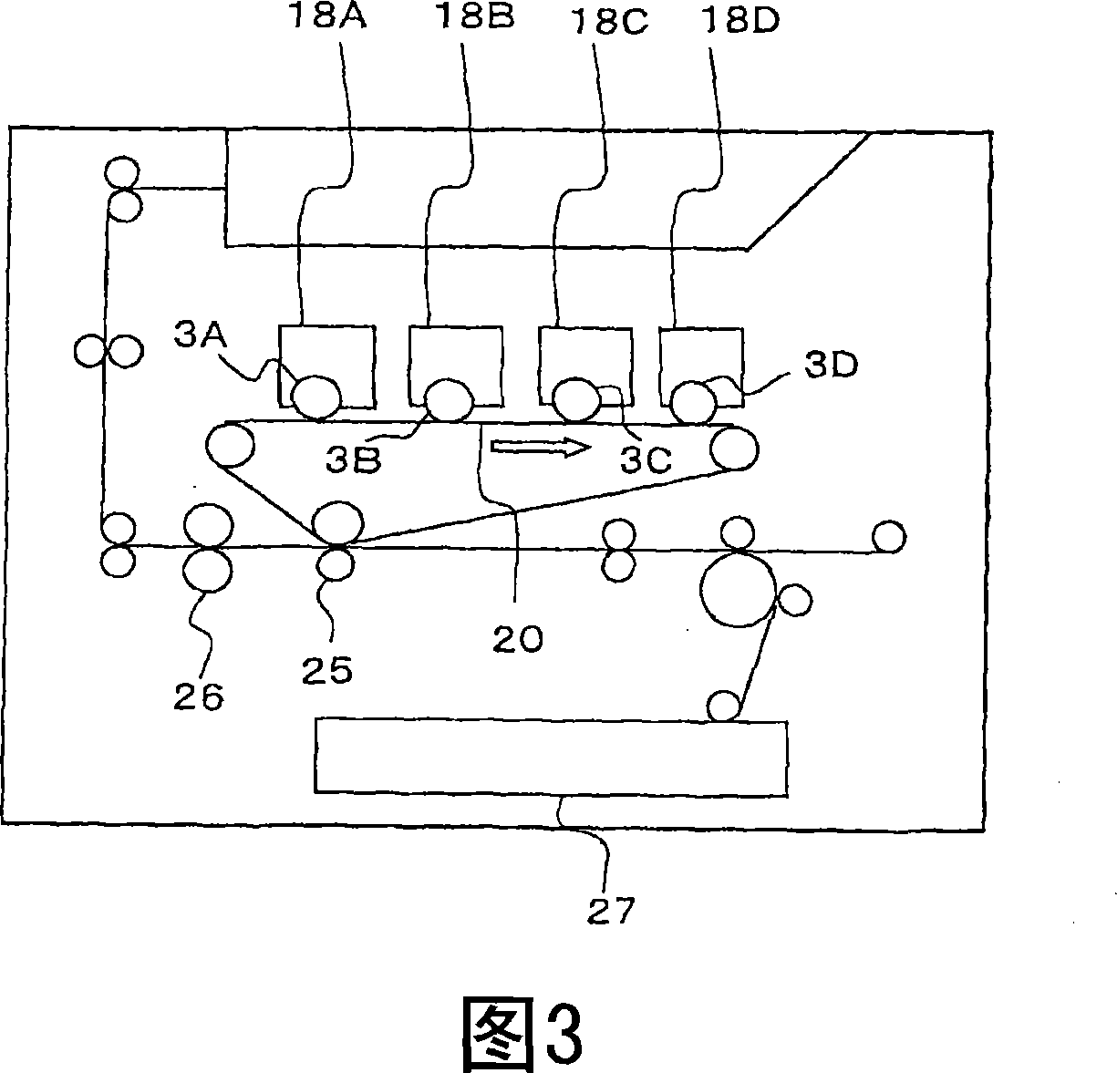
[0060] Hereinafter, a first embodiment of the present invention will be described in detail with reference to the drawings. 1 is an explanatory diagram showing a schematic configuration of an image forming apparatus of a drop-down developing method according to a first embodiment; FIG. 2 is a schematic configuration diagram showing a part of the developing unit in FIG. 1; FIG. A schematic configuration diagram of an example of a unitary tandem color image forming apparatus.
[0061] (image forming device)
[0062] The image forming apparatus of the first embodiment is an image forming apparatus based on a so-called drop-down development method in which a two-component developer including a magnetic carrier 4 and toner 5 is used, and is carried by a magnetic roller 1. The two-component developer forms a thin toner layer 9 on the developing roller 2 to develop the electrostatic latent image formed on the photoreceptor 3 (electrostatic latent image bearing member). As shown in ...
no. 2 approach
[0116] Hereinafter, a second embodiment of the present invention will be described in detail with reference to the drawings. FIG. 7 is an explanatory view showing a schematic configuration of an image forming apparatus of a drop developing method according to the present embodiment. FIG. 8 is a schematic configuration diagram showing a part of the developing unit shown in FIG. 7 . In addition, the same code|symbol is attached|subjected to the same component as 1st Embodiment, and description is abbreviate|omitted.
[0117] (image forming device)
[0118] The image forming apparatus of this embodiment forms an image by the above-mentioned so-called drop development method. As shown in FIG. 7, the image forming apparatus includes a photoreceptor 3 (electrostatic latent image carrier), and around the photoreceptor 3, a charging unit 8, an exposure unit 16, a developing unit 18, a primary transfer unit 22, two A secondary transfer unit 25, a fixing unit 26, a cleaning unit 24, ...
no. 3 approach
[0149] Hereinafter, embodiments of the present invention will be described in detail with reference to the drawings. FIG. 11 is an explanatory diagram showing a schematic configuration of an image forming apparatus of a drop developing method according to an embodiment of the present invention. FIG. 12 is a schematic configuration diagram showing a part of the developing unit shown in FIG. 11 . The same reference numerals are assigned to the same components as those in the first and second embodiments, and explanations thereof will be omitted.
[0150] (image forming device)
[0151] The image forming apparatus of the present invention forms an image by the aforementioned so-called drop development method. As shown in FIG. 11, the image forming apparatus includes the aforementioned photoreceptor 3 (electrostatic latent image carrier), and around the photoreceptor 3, a charging unit 8, an exposure unit 16, a developing unit 18, a primary transfer unit 22, A secondary transfe...
PUM
 Abstract
Description
Claims
Application Information
 - R&D Engineer
- R&D Manager
- IP Professional
- Industry Leading Data Capabilities
- Powerful AI technology
- Patent DNA Extraction
Browse by: Latest US Patents, China's latest patents, Technical Efficacy Thesaurus, Application Domain, Technology Topic.
© 2024 PatSnap. All rights reserved.Legal|Privacy policy|Modern Slavery Act Transparency Statement|Sitemap