System and method for temperature control of electronic equipments

A technology of temperature control and electronic equipment, which is applied in the direction of temperature control using electric methods, can solve the problems of complex, inaccurate reaction temperature, and high cost, and achieve convenient maintenance and management, low engineering cost, and stable and reliable results. Effect

Inactive Publication Date: 2008-08-20
新奇点智能科技集团有限公司
View PDF0 Cites 12 Cited by
  • Summary
  • Abstract
  • Description
  • Claims
  • Application Information

AI Technical Summary

Problems solved by technology

[0004] The problem faced by this method is: when the fan itself fails, the warning information on the device, such as the indicator light or the sound alarm, may not be fed back to the operator in time, because the operator cannot observe the fan installed in the system. equipment
[0006] The problem faced by this method is that the temperature field where the thermally deformed parts are located is very different from the temperature field where the electronic components are located, so the collected information often cannot accurately reflect the working time of the high power consumption devices on the module. temperature, the change of the state of the ventilation hole derived from the thermal deformation part through its own deformation is difficult to achieve the design effect predetermined by the designer
[0008] The problem that adopts this kind of method to face is: existing automatic control technology is often according to an input parameter, such as the temperature of main chip, corresponding adjustment is aimed at the rotating speed of the cooling fan of this chip and the angle of air channel plate (controlling with micro-motor assembly )
The existing thermal design ideas that are compatible with different environments are difficult to solve the high and low temperature problems faced by equipment in specific harsh environments, especially when some parameters of the two environments are completely opposite, such as the low temperature in the airborne environment. Air pressure and high temperature and humidity in the shipboard environment
[0010] For example, in a low-pressure environment, the efficiency of forced convection using air as the heat transfer medium is very low. Even if the fan speed is adjusted to the highest level, it is difficult to effectively dissipate heat from local high-temperature locations.
At this time, it is necessary to make major adjustments to the heat dissipation scheme, including comprehensive adjustments to the fan speed and the path of the air flow. For such a complicated situation, it is difficult to achieve a good heat dissipation effect with a simple automatic adjustment method.
In order to avoid this situation, the heat dissipation method mainly based on conduction and radiation will often lead to a significant increase in cost and equipment weight.
[0011] In addition, in the prior art, it is also proposed to install different temperature adjustment devices for different scenarios where electronic equipment may be used. implement complex problems
[0012] It can be seen from the above description that the starting point of the existing technology is to aim at a certain specific environment, or to be fully compatible with several specific environments, sometimes at the cost of sacrificing the efficiency of the temperature adjustment device, after realizing the reliability of the electronic equipment , it is often difficult to take into account the miniaturization, light weight and low cost of equipment
[0013] It can be seen that if you need to be compatible with the two usage environments, you need to pay high costs, even at the expense of the reliability of electronic equipment

Method used


Image

  • System and method for temperature control of electronic equipments
  • System and method for temperature control of electronic equipments
  • System and method for temperature control of electronic equipments

Examples


Embodiment Construction

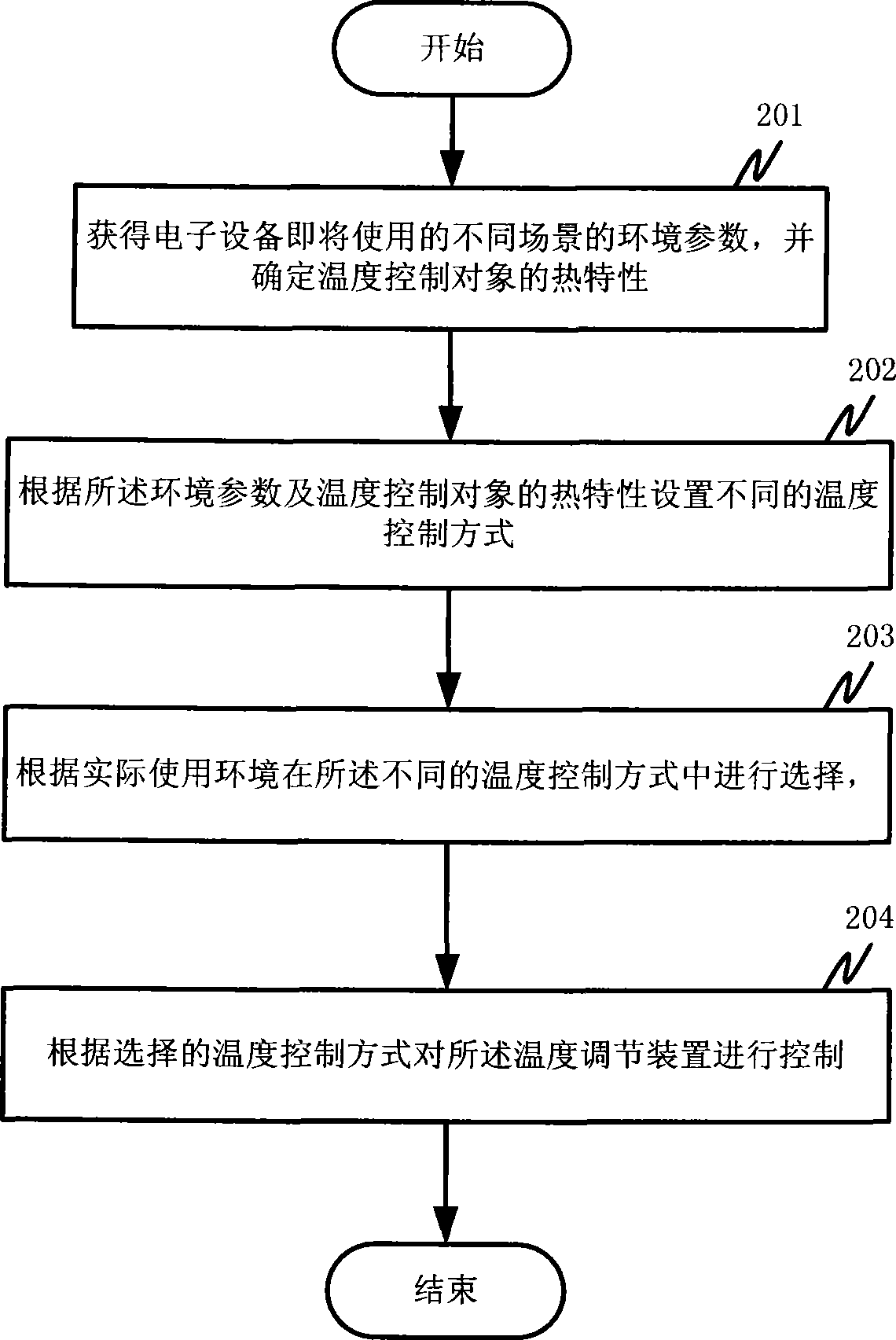
[0047] According to the environmental parameters of the environment where the electronic equipment may be used, and in combination with the characteristics of the temperature control object (that is, the components that need to be temperature-controlled in the electronic equipment), the present invention sets the temperature control methods for the electronic equipment in different use environments, and can be based on According to the needs of the actual environment, use the automatic mode or manual mode to select the temperature control mode.

[0048] Preferred embodiments of the present invention will be described in detail below in conjunction with the accompanying drawings.

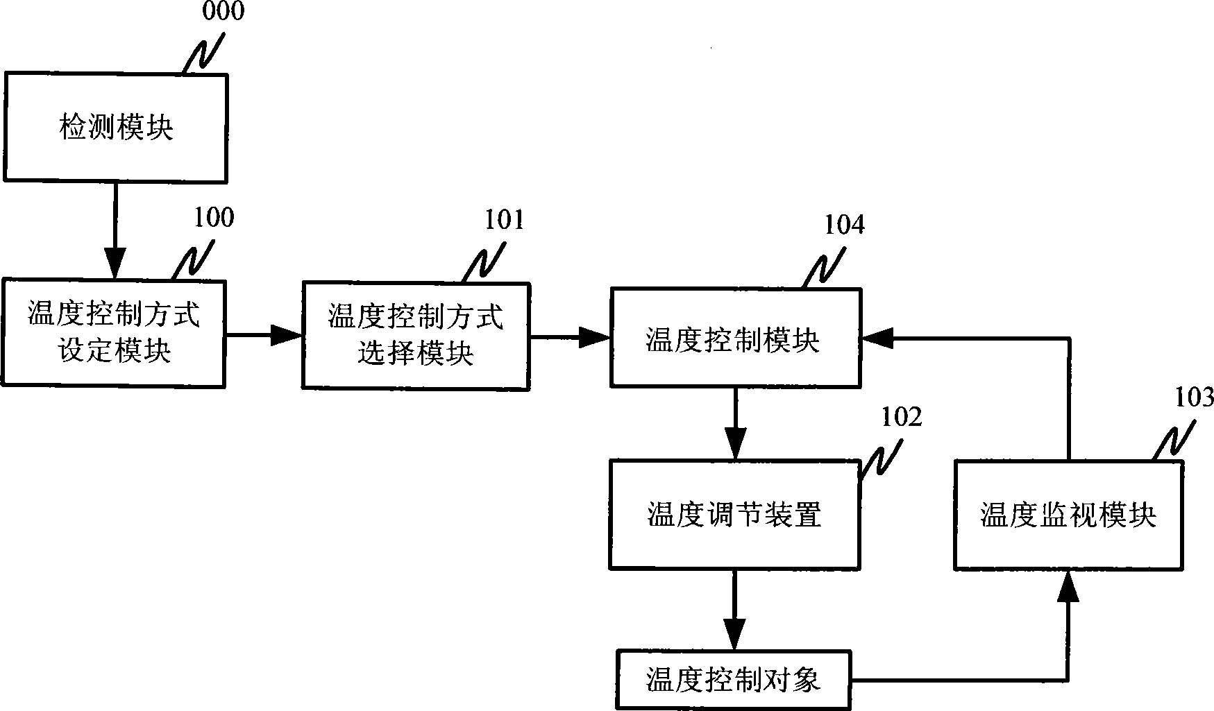
[0049] refer to figure 1 As shown, it is a schematic structural diagram of the system for controlling the temperature of electronic equipment according to the present invention. The system includes: a detection module 000 , a temperature control mode setting module 100 , a temperature control mode s...


PUM


Abstract

The invention discloses a temperature control system and method for electronic appliance. The system controls temperature of electronic appliance by utilizing temperature regulating device. The method comprises the following steps (1) obtaining the environmental parameter of different scenes for electronic appliance and confirming the thermal characteristics of temperature controlled object, (2) setting different temperature control styles according to the environmental parameter and the thermal characteristics of temperature controlled object, (3) choosing different temperature control styles according to actual using environment, (4) controlling the temperature regulating device according to chosen temperature control style. The temperature controlled system and process can satisfy the claim of electronic component temperature control in different environment, and has features such as maturated process engineering, cheap engineering project cost and stable and reliable result.

Description

technical field [0001] The invention belongs to the technical field of electronic equipment application, and in particular relates to a system and method for controlling the temperature of components in electronic equipment. Background technique [0002] Thermal design, that is, temperature control, is usually an issue that needs to be focused on in the environmental reliability design of electronic equipment. A good thermal environment is provided for the chip level, component level, component level, and system level through temperature control technology to ensure that they are in the specified thermal environment. , can work normally and reliably according to the predetermined parameters. In general thermal design, the environment considered is usually fixed, such as indoor environment, vehicle environment, airborne environment or shipboard environment. The temperature regulating device adopted is generally a fan, a heat-deformable part or a micro-motor. [0003] When u...

Claims


Application Information

Patent Timeline
Patent Type & Authority Applications(China)
IPC IPC(8): G05D23/19
Inventor 张辉王西强孟斐
Owner 新奇点智能科技集团有限公司
Why Eureka
Try Eureka