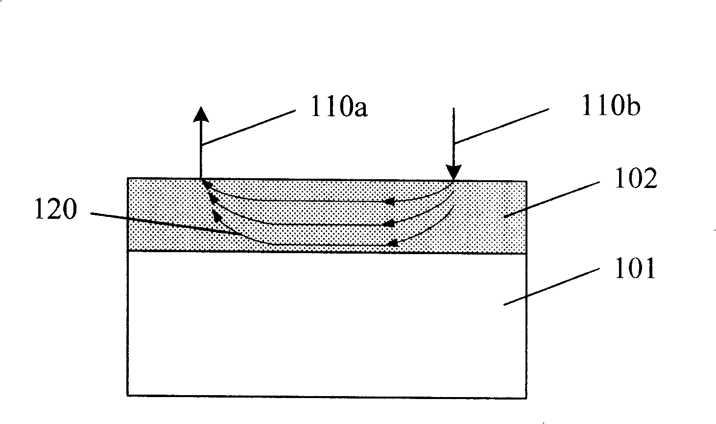
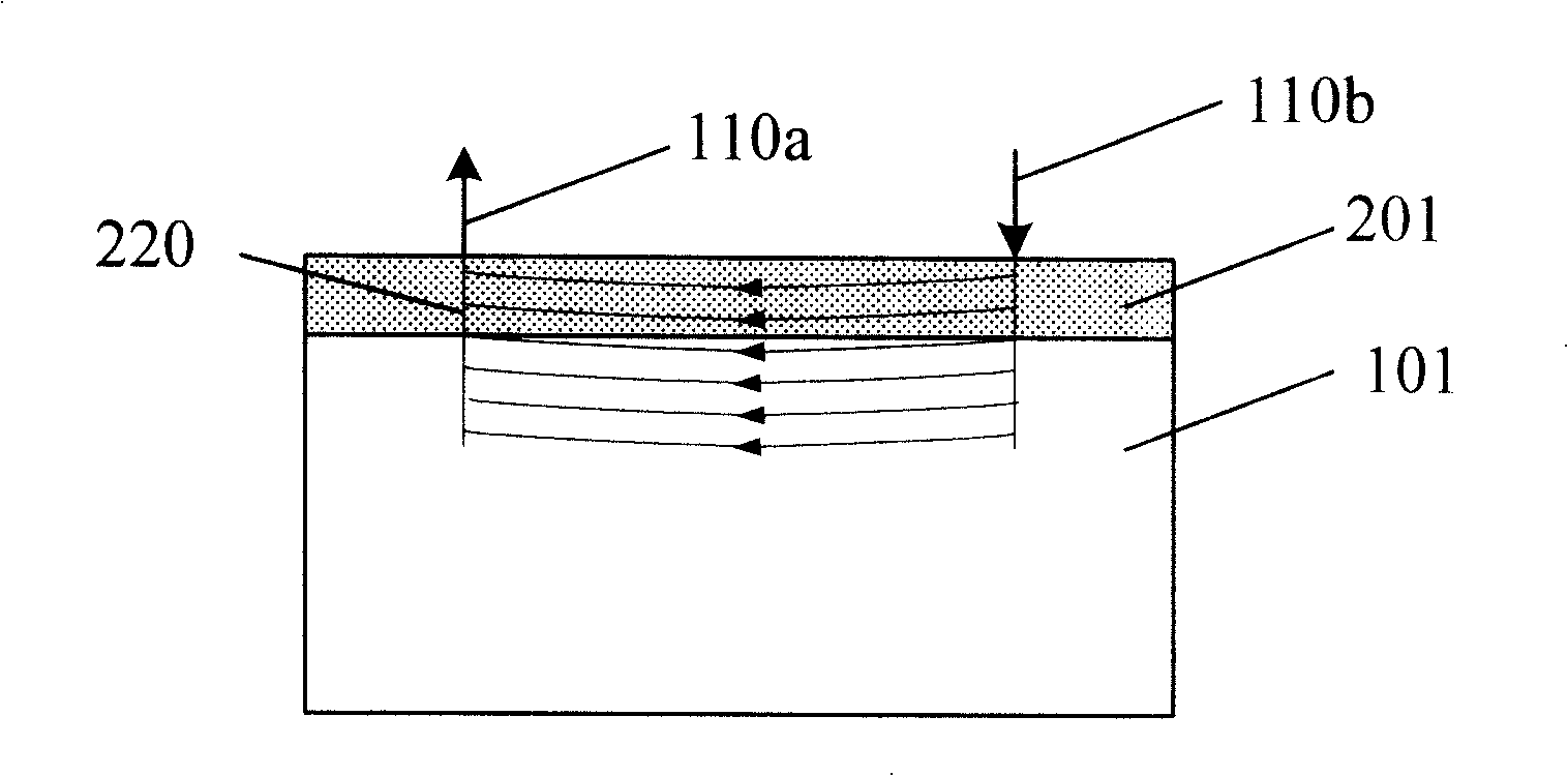
[0036] In order to make the above-mentioned objects, features and advantages of the present invention more obvious and understandable, the specific embodiments of the present invention will be described in detail below with reference to the accompanying drawings.
[0037] The processing method of the present invention can be widely used in many applications, and can be made of many appropriate materials. The following is a preferred embodiment to illustrate, of course, the present invention is not limited to this specific embodiment. The general substitutions well-known to those of ordinary skill within are undoubtedly covered by the protection scope of the present invention.
[0038] Secondly, the present invention is described in detail using schematic diagrams. In detailing the embodiments of the present invention, for ease of explanation, the cross-sectional view showing the device structure will not be partially enlarged according to the general scale and should not be used as a limitation to the present invention. In addition, In actual production, the three-dimensional dimensions of length, width and depth should be included.
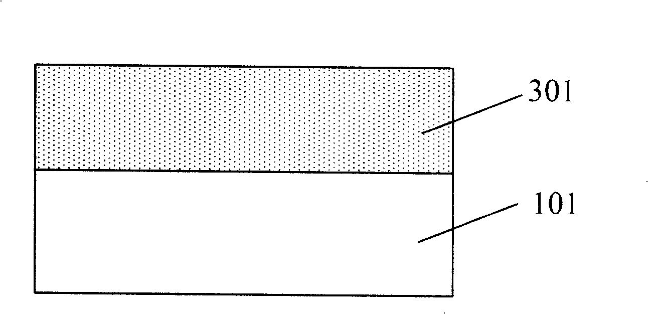
[0039] In order to improve the repeatability and poor accuracy of the monitoring of the shallow junction ion implantation process, the present invention proposes a monitoring test strip for the ion implantation process. image 3 It is a schematic cross-sectional view of the monitoring test piece of the ion implantation process of the present invention, such as image 3 As shown, the monitoring test piece includes a substrate 101 and a pre-doped layer 301 formed in the substrate 101, and the pre-doped layer 301 can be realized by different process methods, such as a diffusion method or an ion implantation method. The impurity type of the substrate 101 is opposite to the impurity type injected by the ion implantation process to be monitored, and the impurity type of the pre-doped layer 301 is the same as the impurity type injected by the ion implantation process to be monitored. That is: when the ion implantation to be monitored is n-type, the substrate is p-type, and the impurity of the pre-doped layer is n-type, such as phosphorus or arsenic; when the ion implantation to be monitored is p-type, the liner The bottom is n-type, and the impurity of the pre-doped layer is p-type, such as boron. In addition, the thickness of the pre-doped layer is usually greater than the implantation depth of the ion implantation process to be monitored, at least Above, if Etc., to ensure that the probe does not pass through it to contact the underlying substrate layer; as for the upper limit of its thickness, it is only limited by the doping thickness that can be achieved by the doping process.
[0040] Figure 4 It is a schematic cross-sectional view of the monitoring test strip of the ion implantation process of the present invention after shallow junction ion implantation, such as Figure 4 As shown, after the shallow junction ion implantation to be monitored, a shallow junction ion implantation layer 201 is formed in the pre-doped layer 301, and its thickness is small. When the resistance value is tested by the four-probe method, the probe It is easy to pass through this layer. If the monitoring test piece used does not have the pre-doped layer 301, the measured resistance will be affected by the substrate under the shallow junction ion implantation layer, resulting in inaccurate resistance test results. In the present invention, a thicker pre-doped layer 301 is added, so that even if the probe passes through the shallow junction ion implantation layer 201 during the test, it will not reach through the thicker pre-doped layer 301. The substrate 101 prevents the detected square resistance value from being affected by the substrate resistance whose resistance value cannot be determined. In addition, because the doping condition of the pre-doped layer 301 is determined, when the shallow junction ion implantation process is analyzed according to the measured square resistance value, its influence (determined resistance value) can be removed to achieve accurate and repeatable Monitor the shallow junction ion implantation process.
[0041] Figure 5 It is a schematic diagram of the four-probe method of the present invention for detecting the monitoring test piece of the shallow junction ion implantation process, such as Figure 5 As shown, when the shallow junction ion implantation process is detected by the four-probe method, because the shallow junction ion implantation layer 201 is thin, the probe may pass through the layer and contact the lower pre-doped layer 301, resulting in the probe 110a The test current 510 between 110b and 110b not only passes through the shallow junction ion implantation layer 201 to be tested, but may also pass through the pre-doped layer 301 underneath. However, because the pre-doped layer 301 has a large thickness, the probe will no longer The underlying substrate 101 is contacted. At this time, the measured sheet resistance value is the parallel value of the resistance of the shallow junction ion implantation layer 201 and the pre-doped layer 301. Among them, the impurity amount of the pre-doped layer 301 is determined, and its sheet resistance value is also determined. Therefore, the sheet resistance value of the shallow junction ion implantation layer 201 can be derived from the sheet resistance value measured by the four-probe method, and The accuracy and repeatability of the test are good.
[0042] In addition, the impurity concentration of the pre-doped layer 301 can be set to be much lower than that of the shallow junction ion implantation layer 201 to be monitored. In this way, the resistance value of the pre-doped layer 301 will be much larger than that of the shallow junction ion implantation layer 201. The resistance value can basically be considered that the measured square resistance value is the resistance value of the shallow junction ion implantation layer 201, and the monitoring of the shallow junction ion implantation process is more convenient and direct.
[0043] The monitoring test strip of the ion implantation process of the present invention is described in detail above, and the following describes how to use the monitoring test strip of the ion implantation process of the present invention to monitor the shallow junction ion implantation process. Figure 6 It is a flow chart of the monitoring method of the ion implantation process of the present invention, the following is combined Figure 6 Give specific instructions.
[0044] First, a substrate is provided (S601). The impurity type doped on the substrate is opposite to the impurity type implanted by the shallow junction ion implantation process to be monitored. In this embodiment, it is assumed that the shallow junction ion implantation process is n-type arsenic ( As), the substrate used to make the monitoring test piece (such as a silicon wafer) should be p-type.
[0045] Next, a pre-doping process is performed in the substrate to form a pre-doping layer (S602). The pre-doping treatment in this step can be implemented by a diffusion process or an ion implantation process. In this embodiment, the latter is used, which may also be referred to as a pre-ion implantation process. Since the impurity type of the pre-doped layer formed in this step should be the same as the impurity type implanted by the ion implantation process to be monitored, in this embodiment, the pre-ion implantation also needs to use n-type impurities, such as phosphorus.
[0046] In order to prevent the probe from passing through the pre-doped layer, the thickness of the pre-doped layer formed by the pre-ion implantation in this step is required to be thicker, at least larger than the implantation depth of the shallow junction ion implantation process to be monitored, usually at least at Above, if Wait to ensure that the probe does not pass through it and touch the underlying substrate layer. Therefore, the energy used for pre-ion implantation in this step is usually relatively large, and energy greater than 5 KeV is generally selected, such as 10 KeV, 100 KeV, 1000 KeV, 3000 KeV, etc. In addition, in order to make the resistance value of the pre-doped layer so large that it can be ignored in the subsequent sheet resistance test, the implant dose is usually set to be much smaller than the dose of the shallow junction ion implantation process to be monitored, such as smaller 1 to 3 orders of magnitude.
[0047] Figure 7 It is a schematic diagram of the measured impurity distribution of the pre-doped layer in the specific embodiment of the present invention, where the dopant selected for the pre-doped layer is phosphorus, and the implantation energy used is 30KeV, such as Figure 7 As shown, the abscissa is the depth of the monitoring test piece, and the ordinate is the impurity concentration in the monitoring test piece. In the figure, 701 is the curve of the impurity concentration of the pre-doped layer changing with the depth of the test piece. It can be seen that when the depth of the test piece is monitored When around, the impurity concentration reaches the peak value-1e19/cm 3 , When the depth of the monitoring test piece reaches When around, the impurity concentration has dropped to 1e18/cm 3 , It can be considered that the thickness of the pre-doped layer is about about. When the four probe method is used for testing later, the probe usually cannot pass through this thickness, so it can be ensured that the probe will not touch the underlying substrate with a small resistance and no specific resistance.
[0048] So far, the test strip for monitoring the shallow junction ion implantation process has been prepared, and it can be used to monitor the shallow junction ion implantation process.
[0049] When performing shallow junction ion implantation to be monitored, the above-mentioned monitoring test piece is put in, and shallow junction ion implantation is performed on it at the same time (S603). In this embodiment, this step of ion implantation is relatively shallow, and is used to form n-type source/drain. The implanted impurity is arsenic (As), the implantation energy is 2KeV, and the implantation depth is about. Picture 8 In order to measure the impurity distribution of the shallow junction ion implantation layer in the specific embodiment of the present invention, the test piece used has not been pre-doped, that is, no pre-doped layer is formed. Such as Picture 8 As shown, the abscissa is the depth of the sample, and the ordinate is the concentration of impurities in the sample. In the figure, 801 is the curve of the impurity concentration of the shallow junction ion implantation layer with the depth of the sample. It can be seen that when the depth of the sample reaches Around, the impurity concentration reached the peak value-1e21/cm 3 , When the depth of the sample reaches When around, the impurity concentration drops to 1e18/cm 3 , It can be considered that the implantation depth of this shallow junction ion implantation process is about about.
[0050] Figure 7 with Picture 8 The test results shown are completed by secondary ion mass spectroscopy (SIMS), which can detect the impurity distribution after ion implantation, and there is no need to worry about the test results being incorrect due to the probe contacting the substrate. accurate. However, compared with the four-probe method, it is not advisable to use this method to monitor the ion implantation process in production. The reason is that the SIMS method is used to monitor the ion implantation. On the one hand, it is time-consuming: SIMS detection is slower and impossible to be timely Provide information on the ion implantation process; on the other hand, it costs money: the cost of SIMS detection is much more expensive than the four-probe method. Therefore, it is hoped that the four-probe method can be used to monitor the shallow junction ion implantation process in real time.
[0051] After the shallow junction ion implantation, thermal annealing is performed on the monitoring test piece (S604) to activate the impurities implanted in the pre-ion implantation and shallow junction ion implantation steps. For example, it can be subjected to rapid thermal annealing at 1000°C under the protection of nitrogen.
[0052] Next, the test strip is tested by the four-probe method (S605). Since the substrate of the monitoring test piece contains a pre-doped layer with a large thickness, the probe will not pass through the pre-doped layer to reach the substrate during the detection process, thus avoiding the small and uncertain resistance value The substrate interferes with the test results.
[0053] Since the impurity concentration of the pre-doped layer is determined, and it is repeated from chip to chip, when the four-probe method detects the square resistance, the difference of the pre-doped layer will not cause the change of the square resistance between the chips. Therefore, it can be considered that as long as the shallow junction ion implantation process is consistent, the sheet resistance value between the sheets should be consistent. On the contrary, if the detected sheet resistance value is inconsistent, it can indicate that the shallow junction ion implantation process has a deviation. In this way, accurate monitoring of the shallow junction ion implantation process can be realized.
[0054] Experiments have confirmed that when using traditional monitoring test strips without a pre-doped layer Picture 8 When the shallow junction ion implantation shown in Figure 1 is used for monitoring, the measured sheet resistance value (including chip to chip and between the same chip) has a deviation of about 50%. This is because the probe sometimes touches the liner. At the end, sometimes the substrate is not touched, resulting in a large change in the measured square resistance; on the other hand, due to the inconsistency of the substrate resistance between the sheets, even if the probe is fully in contact with the substrate, There may be large deviations in the detection results of the sheet resistance between the sheets. However, after the monitoring test strip with the pre-doped layer of the present invention is used, the above two situations will no longer occur. As a result, the deviation of the sheet resistance value between the sheets and the same sheet obtained by the test is reduced to 2.4 Within %, the test repeatability is greatly improved, and the test results can more accurately reflect the real situation of the shallow junction ion implantation process.
[0055] In addition, although the pre-doped layer is much thicker than the shallow junction ion implantation layer (for example, it is about 3 times thicker in this embodiment), its doping concentration is much smaller than that of the shallow junction ion implantation layer (as in this example). In the embodiment, it is two orders of magnitude smaller). Therefore, the resistance of the pre-doped layer is still much higher than that of the shallow junction ion implantation layer (about two orders of magnitude). At this time, the sheet resistance value measured by the four-probe method (which is obtained by paralleling the sheet resistance of the pre-doped layer and the sheet resistance of the shallow junction ion implantation layer) basically represents the sheet resistance value of the shallow junction ion implantation layer. The resistance value of the pre-doped layer fluctuates slightly, which has little effect on the final test result, and can still more truly reflect the implantation situation of the shallow junction ion implantation process.
[0056] The above monitoring method illustrates the monitoring of the n-type shallow junction ion implantation process. In other embodiments of the present invention, the p-type shallow junction ion implantation can also be monitored. At this time, the pre-doping treatment (may be pre-doping) The impurity doped in the pre-doped layer formed by the diffusion method, or the pre-ion implantation method, etc.) is also p-type, such as boron. The monitoring process is similar to the monitoring process of the n-type shallow junction ion implantation process described above, and will not be repeated here.
[0057] Note that as long as a thicker pre-doped layer is formed in the monitoring test piece to shield the underlying material from the possible influence of the detection result of the ion implantation process to be monitored, it should fall within the protection scope of the present invention.
[0058]Although the present invention is disclosed as above in preferred embodiments, it is not intended to limit the present invention. Any person skilled in the art can make possible changes and modifications without departing from the spirit and scope of the present invention. Therefore, the present invention The protection scope of shall be subject to the scope defined by the claims of the present invention.