
Conjecture method of stator magnetic linkage oriented AC motor rotation velocity and rotor position

A technology of stator flux linkage orientation and rotation speed, which is applied in electronic commutation motor control, generator control, motor generator control, etc. practical effect

Active Publication Date: 2008-08-20
JIANGSU REYA ELECTRIC
View PDF1 Cites 33 Cited by
  • Summary
  • Abstract
  • Description
  • Claims
  • Application Information

AI Technical Summary

Problems solved by technology

At the same time, for the current variety of AC rotating motors, it is hoped that there will be a unified, simple and clear algorithm and logic, only need to adjust a small number of parameters to adapt to the sensorless vector control of various types of AC rotating motors, To change the current situation that there are many types of power conversion devices for AC motor drives and inconvenient to use

Method used


Image

  • Conjecture method of stator magnetic linkage oriented AC motor rotation velocity and rotor position
  • Conjecture method of stator magnetic linkage oriented AC motor rotation velocity and rotor position
  • Conjecture method of stator magnetic linkage oriented AC motor rotation velocity and rotor position

Examples


Embodiment Construction

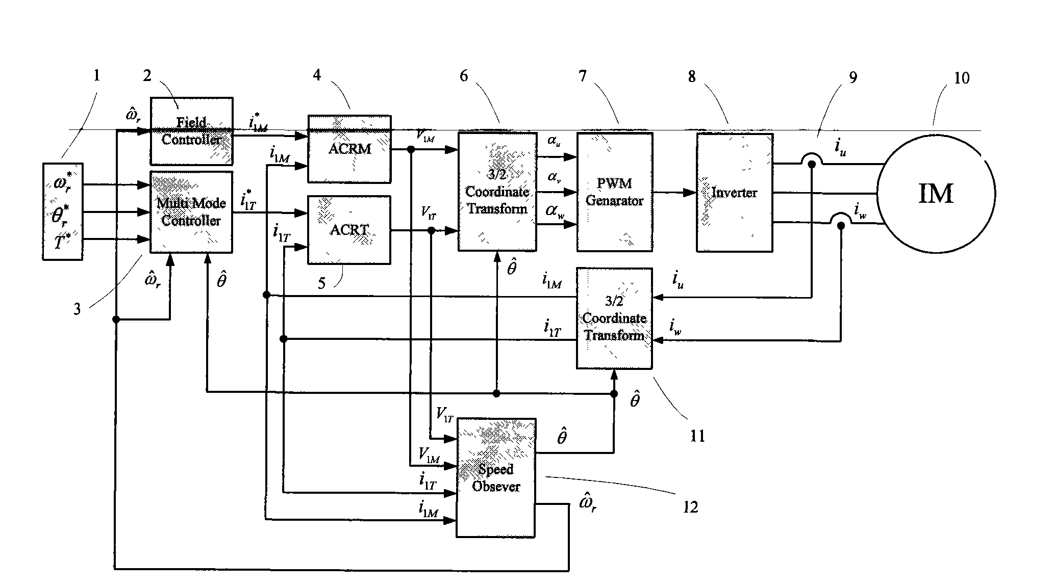
[0113] The technical solution of the present invention will be further elaborated below according to the accompanying drawings of the description. figure 1 Shown is the MT rotating coordinate system based on the stator flux orientation vector control of the stator flux linkage. This coordinate system positions the excitation axis M axis on the stator flux linkage vector and keeps synchronous with it; at the same time, the torque axis T axis leads the M axis by 90 Spend. The present invention selects the stator flux linkage oriented vector control system, so that the stator flux linkage becomes the controlled target flux linkage.

[0114] All parameters of the stator and rotor of the motor, such as stator voltage and stator current, can be decomposed into M-axis components and T-axis components in the MT rotating coordinate system. Among them, because the M-axis is consistent with the controlled target flux vector, the M-axis components are related to the motor flux linkage; w...


PUM


Abstract

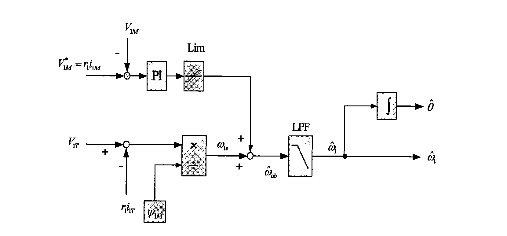
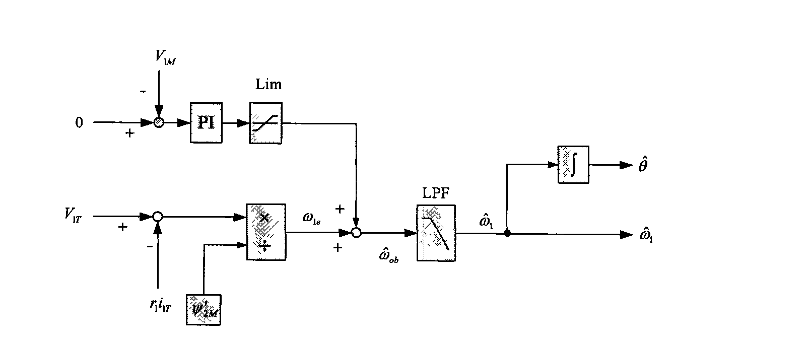
The target of the invention is an asynchronous machine stator magnetic linkage flux-oriented vector control system. The torque voltage V1T outputted by the torque current control loop is used for calculating out the basic estimated value omega1e of the rotating angular velocity of the stator magnetic linkage. At the same time when the excitation voltage reference value V1M<*> is calculated out the adjusting angular velocity delta omega is obtained by calculating the comparison of proportional integral of the error between V1M<*> and the output excitation voltage V1M. The estimated value omega1 of the rotating angular velocity of the stator magnetic linkage can be obtained by adding the delta omega with the omega1e, and at the same time the estimated value theta of the phase angle of the rotational coordinate system of the electric motor MT can be obtained after executing integral operation to the omega1. Finally by real-time dynamically calculating and adjusting the magnitude of the angular velocity delta omega with a high speed the control system obtains the purpose that the MT rotational coordinate system is kept with a synchronous state to the actual rotary speed of the controlled objective magnetic linkage of the alternating current rotating electric machine and the phases are always kept consistent, thereby realizing the vector controlling of the no-velocity position sensor of the asynchronous machine.

Description

technical field [0001] The invention belongs to the technical field of motor control, in particular to a vector control system without a speed position sensor of an AC rotary asynchronous motor oriented by stator flux linkage. Background technique [0002] With the continuous advancement of high-power semiconductor component technology and the rapid increase in the computing speed of the micro-CPU for control, high-power DC / AC conversion devices are widely used in industrial production and civilian products to drive various types of AC rotation The motor is driven by a variable speed motor to achieve energy saving, high precision control and other effects. [0003] In the drive of asynchronous motors, the well-known V / f constant control method (such as patent document 1 and patent document 2) is widely used, and there are also controls such as extending certain functions on the V / f constant control (such as patent document 3). method. However, since the constant V / f contro...

Claims


Application Information

Patent Timeline
Patent Type & Authority Applications(China)
IPC IPC(8): H02P21/14H02P21/18
Inventor 戴政
Owner JIANGSU REYA ELECTRIC
Learn More