
Thrust vector controlled continuous detonation rocket-based engine and aircraft

A thrust vector control and engine technology, applied in the aviation field, can solve the problems of poor engine propulsion performance and complex structure

Inactive Publication Date: 2019-11-19
PLA PEOPLES LIBERATION ARMY OF CHINA STRATEGIC SUPPORT FORCE AEROSPACE ENG UNIV
View PDF10 Cites 0 Cited by
  • Summary
  • Abstract
  • Description
  • Claims
  • Application Information

AI Technical Summary

Problems solved by technology

[0005] The purpose of the present invention is to provide a continuous detonation rocket-based engine and aircraft with thrust vector control, so as to solve technical problems such as poor propulsion performance and complex structure of the engine in the prior art

Method used


Image

  • Thrust vector controlled continuous detonation rocket-based engine and aircraft
  • Thrust vector controlled continuous detonation rocket-based engine and aircraft
  • Thrust vector controlled continuous detonation rocket-based engine and aircraft

Examples


Embodiment Construction

[0057] The technical solutions of the present invention will be clearly and completely described below in conjunction with the accompanying drawings. Apparently, the described embodiments are some of the embodiments of the present invention, but not all of them. Based on the embodiments of the present invention, all other embodiments obtained by persons of ordinary skill in the art without making creative efforts belong to the protection scope of the present invention.

[0058]In the description of the present invention, it should be noted that the terms "center", "upper", "lower", "left", "right", "vertical", "horizontal", "inner", "outer" etc. The indicated orientation or positional relationship is based on the orientation or positional relationship shown in the drawings, and is only for the convenience of describing the present invention and simplifying the description, rather than indicating or implying that the referred device or element must have a specific orientation, o...


PUM


Abstract

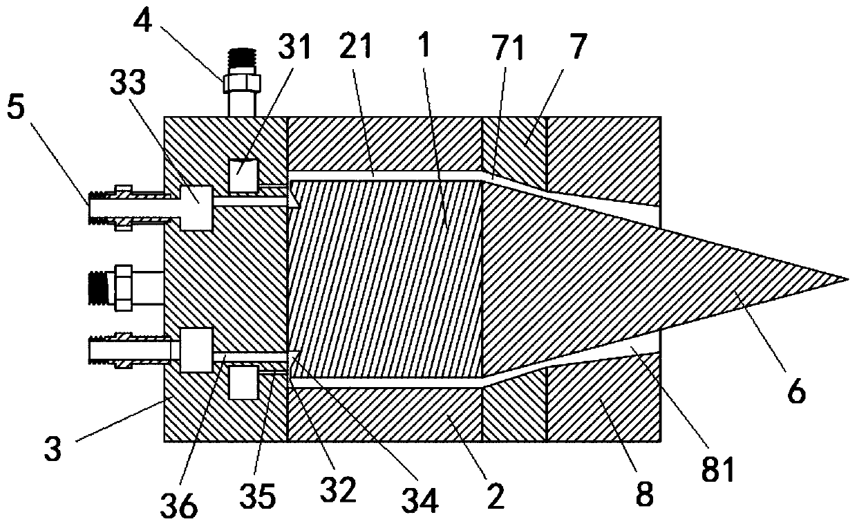
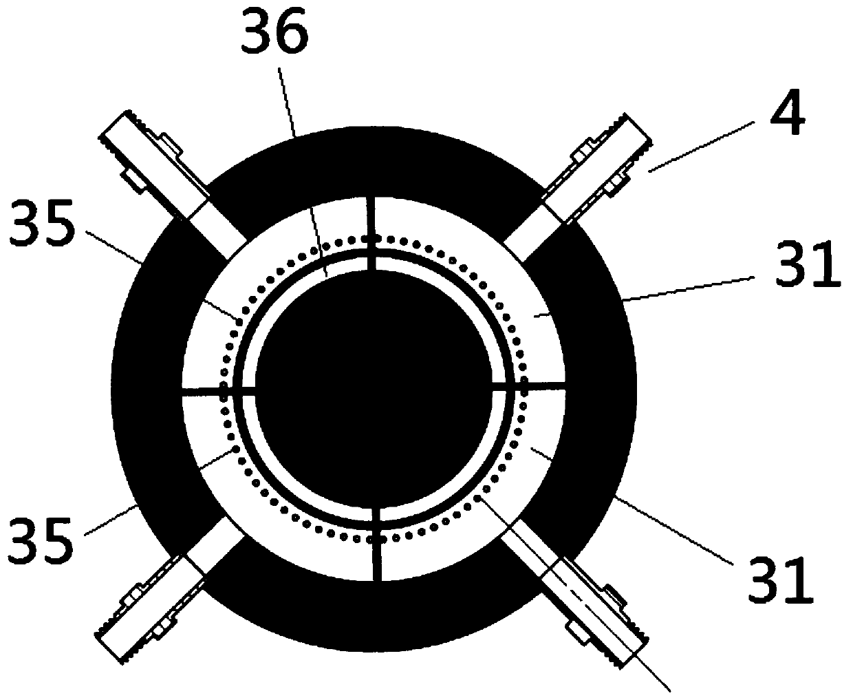
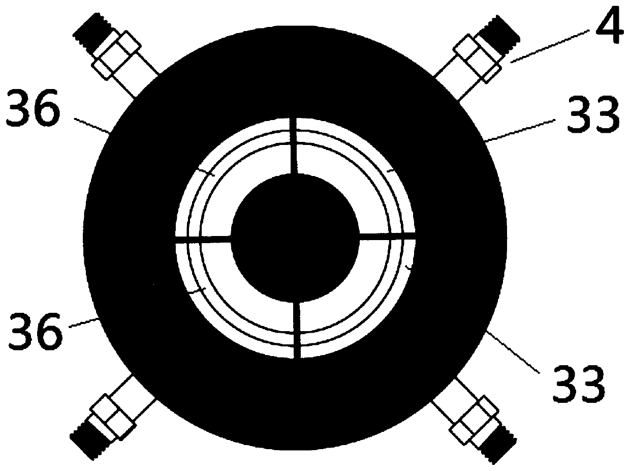
The invention provides a continuous knocking rocket-based engine controlled by thrust vector and a flight vehicle and relates to the technical field of aviation. The continuous knocking rocket-based engine comprises an inner core body. An outer cylinder body is provided with a hollow cavity penetrating in the axial direction and used for sleeving outside the inner core body. A first gap is formedbetween the outer wall of the inner core body and the inner wall of the outer cylinder body. At least one pre-knocking pipe structure is arranged on the outer cylinder body. A gas collecting cavity end cover is arranged at the head end of the inner core body and the outer cylinder body and connected with the inner core body and the outer cylinder body. A fuel inlet is formed in the side wall of the gas collecting cavity end cover. A ring-shaped fuel cavity is formed in the gas collecting cavity end cover. The ring-shaped fuel cavity is partitioned into at least two fuel unit cavities in the peripheral direction. The end face of the gas collecting cavity end cover is provided with an oxidizing agent inlet. An oxidizing agent cavity is formed in the gas collecting cavity end cover. The oxidizing agent cavity is partitioned into at least two oxidizing agent unit cavities corresponding to the fuel unit cavities in the peripheral direction.

Description

technical field [0001] The invention relates to the field of aviation technology, in particular to a thrust vector controlled continuous detonation rocket-based engine and an aircraft. Background technique [0002] The rocket launcher is used to send artificial earth satellites, manned spacecraft, space stations or interplanetary probes into predetermined orbits. The last stage has an instrument cabin, which houses the guidance and control system, telemetry system and launch site safety system. [0003] In the design and manufacture of launch vehicles, reasonable adjustment of engine thrust is a necessary means to achieve active control capabilities such as flight environment control and flight trajectory optimization of launch vehicles. Not only liquid engines must have thrust adjustment capabilities, but solid engines must also pass reasonable design. for thrust control. [0004] However, in the prior art, the propulsion performance is poor and the structure is complex i...

Claims


Application Information

Patent Timeline
Patent Type & Authority Patents(China)
IPC IPC(8): F02K9/42F02K9/44F02K9/62F02K9/80
CPCF02K9/42F02K9/44F02K9/62F02K9/80
Inventor 石天一聂万胜郭康康陈朋苏凌宇林伟刘瑜
Owner PLA PEOPLES LIBERATION ARMY OF CHINA STRATEGIC SUPPORT FORCE AEROSPACE ENG UNIV
Learn More