
Method and apparatus for fluid-liquid reactions

An equipment, fluid technology, applied in the field of fluid-liquid reaction, which can solve the problems of unfavorable after-sales service, flexibility and poor reactivity

Inactive Publication Date: 2008-08-20
NITECH SOLUTIONS LTD
View PDF1 Cites 9 Cited by
  • Summary
  • Abstract
  • Description
  • Claims
  • Application Information

AI Technical Summary

Problems solved by technology

[0012] iv) Poor flexibility and reactivity, thus detrimental to after-sales service
[0013] Until now, there has been no feasible process to effectively control low-volume hydrogenation product costs in line with real requirements that are not distorted by inadequate supply chains

Method used


Image

  • Method and apparatus for fluid-liquid reactions
  • Method and apparatus for fluid-liquid reactions
  • Method and apparatus for fluid-liquid reactions

Examples


Embodiment Construction

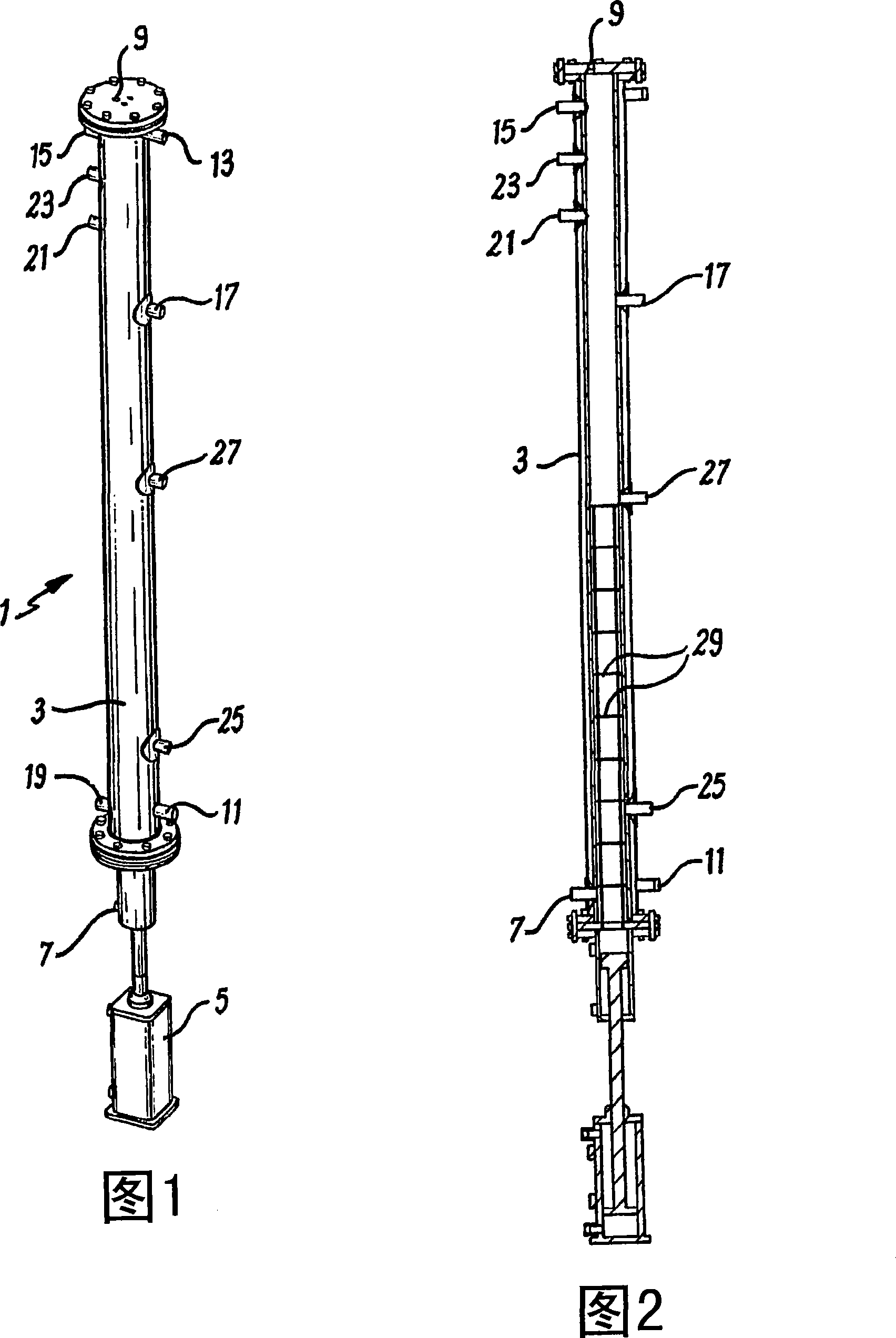
[0088] Figure 1 illustrates a reactor assembly 1 comprising a column 3, a piston 5, which in this example is equipped with a pneumatic hammer.

[0089] Arranged along the length of the shaft 3 are a number of inlet and outlet ports designed to allow the addition of reactants to and removal of products from the reactor, and additionally provide means for varying the temperature and pressure of the reactor. Detection device and method. In Figure 1, the hydrogen inlet 7 and inlet / outlet 9 are illustrated along with the reactant inlet 15, heating or coolant inlet 11 and heating or coolant outlet 13, product return port 19, product outlet 17, high and low level sensors 23 and 25, thermocouple 27 and pH sensor 21.

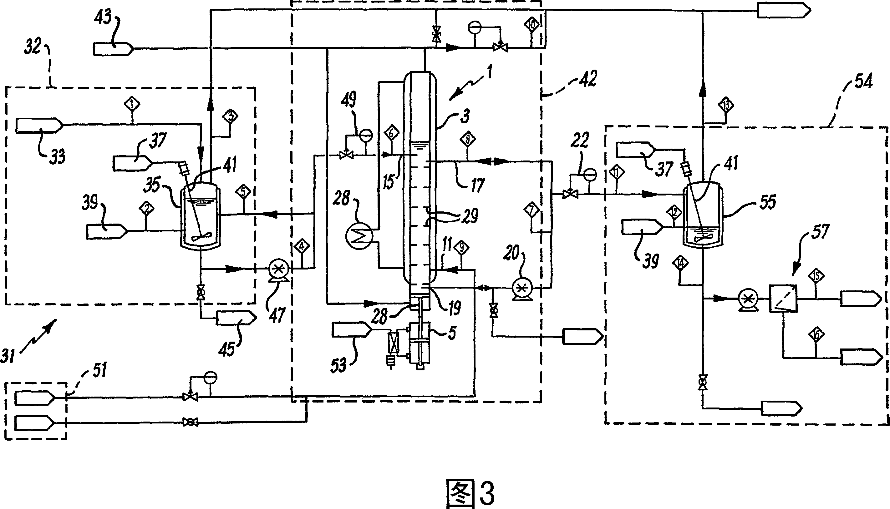
[0090] Figure 2 is a cross-sectional view of the reactor assembly of Figure 1 illustrating, in addition to the features of Figure 1 , fixed baffles 29 spaced along the length of the reactor. Furthermore, a pneumatic hammer 5 is shown. The pneumatic hammer 5 uses compr...


PUM


Abstract

A method and apparatus for fluid-liquid reactions including gas-liquid and liquid-liquid reactions. The method and apparatus is suitable for mixing a fluid phase species and a liquid phase species to facilitate chemical reaction between said phases. The apparatus comprises a reactor vessel with a plurality of orificed plates and flow control means which initiates and maintains uniform mixing and efficient dispersion of a fluid-liquid mixture within the reactor vessel.

Description

technical field [0001] The present invention relates to a method and apparatus for fluid-liquid reactions. Background technique [0002] Fluid-liquid reactions can include gas-liquid and liquid-liquid reactions such as: hydrogenation, hydroformylation, oxidation, reduction, chlorination, deodorization, fermentation, and aerobic treatment; liquid-liquid reactions such as acid in aromatic nitration use of acids or bases to hydrolyze nitriles to amides; and use of acids or bases to hydrolyze amides; use of solvents in transesterification; use of molten fluids in polyurethane dispersions; and use of supersaturated fluids in gas hydrates use. [0003] Performing gas-liquid reactions in mass production is a well-known field. The above processes generally involve the use of stirred reaction tanks in which the fluids are mixed by one or more impellers located in fixed positions inside the tank with baffles. The gas is injected into the reactor by means of a sparger or spargers. ...

Claims


Application Information

Patent Timeline
Patent Type & Authority Applications(China)
IPC IPC(8): B01J19/18B01J19/28
CPCB01J19/285B01J19/2425B01J19/006B01F5/0688B01J19/242B01J8/065B01F11/0071B01J10/007B01J19/185B01J2219/00777B01J2208/0084B01J2208/00814B01F5/0685B01J8/06B01J2219/00162B01J4/004B01J8/16B01F25/4512B01F25/4521B01F31/65B01J19/2405B01J19/2415B01F23/20
Inventor 倪雄伟A·菲奇I·莱尔德
Owner NITECH SOLUTIONS LTD
Learn More