Valve timing regulation device

A technology for adjusting devices and valve timing, which is applied to valve devices, engine components, machines/engines, etc. It can solve problems such as poor assembly, falling off, and high processing accuracy, and achieve excellent manufacturability, easy manufacturing, and improved processing and assembly. sexual effect

Inactive Publication Date: 2008-08-20
MITSUBISHI ELECTRIC CORP
View PDF2 Cites 11 Cited by
  • Summary
  • Abstract
  • Description
  • Claims
  • Application Information

AI Technical Summary

Problems solved by technology

[0006] Second, as shown in Patent Document 1, when a plate-shaped stopper is inserted into a groove formed in a direction perpendicular to the locking pin receiving hole to catch the coil spring from flying out, the processing of the groove requires high labor force. Precision
In addition, since the plate-shaped stopper is inserted into the groove after inserting the lock pin and the coil spring into the housing hole from the radially outer side, the assemblability is poor.
[0007] The third type is that when the coil spring is caught by the stop member that is pressed into the locking pin receiving hole from the radially outer side, it may fall off due to the centrifugal force in the high-speed rotation area, or it may be caused by vibration, etc. loosen and cause shedding
In addition, engineering management of press-fit force and press-fit dimensions is required
[0008] The fourth type, as shown in Patent Document 2, when using the groove wall surface of the housing to catch the coil spring flying out, the coil spring must be inserted into the escape groove together with the locking pin in a compressed state, so the assembly is poor.
[0011] Since the conventional valve timing adjustment device is structured as above, various engaging structures are used to lock the coil spring and fly out. Problems such as detachment due to centrifugal force or slack due to vibration, etc., need for engineering management of press-fit force and press-fit dimensions

Method used


Image

  • Valve timing regulation device
  • Valve timing regulation device
  • Valve timing regulation device

Examples


Embodiment Construction

[0027] Next, in order to explain the present invention in more detail, the best mode for carrying out the present invention will be described with reference to the drawings.

[0028] Implementation form 1.

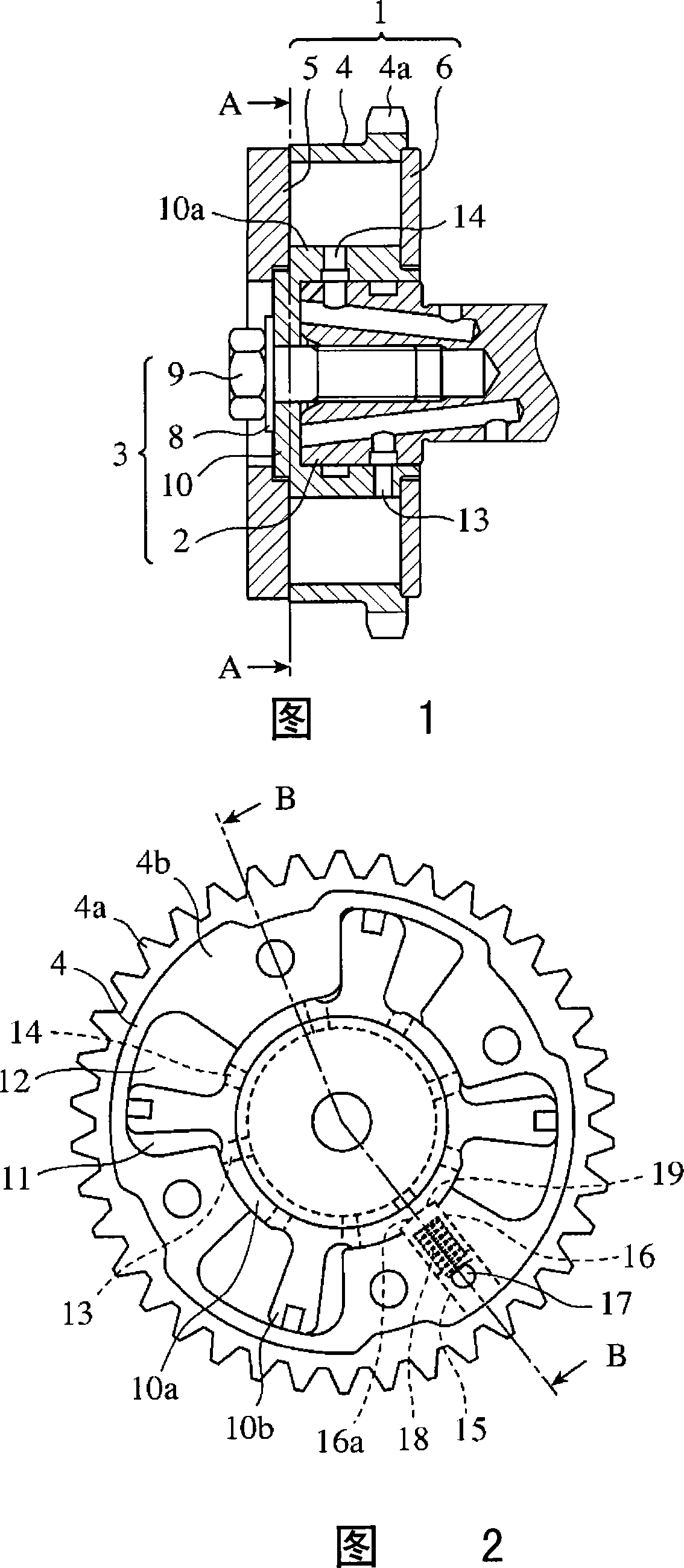
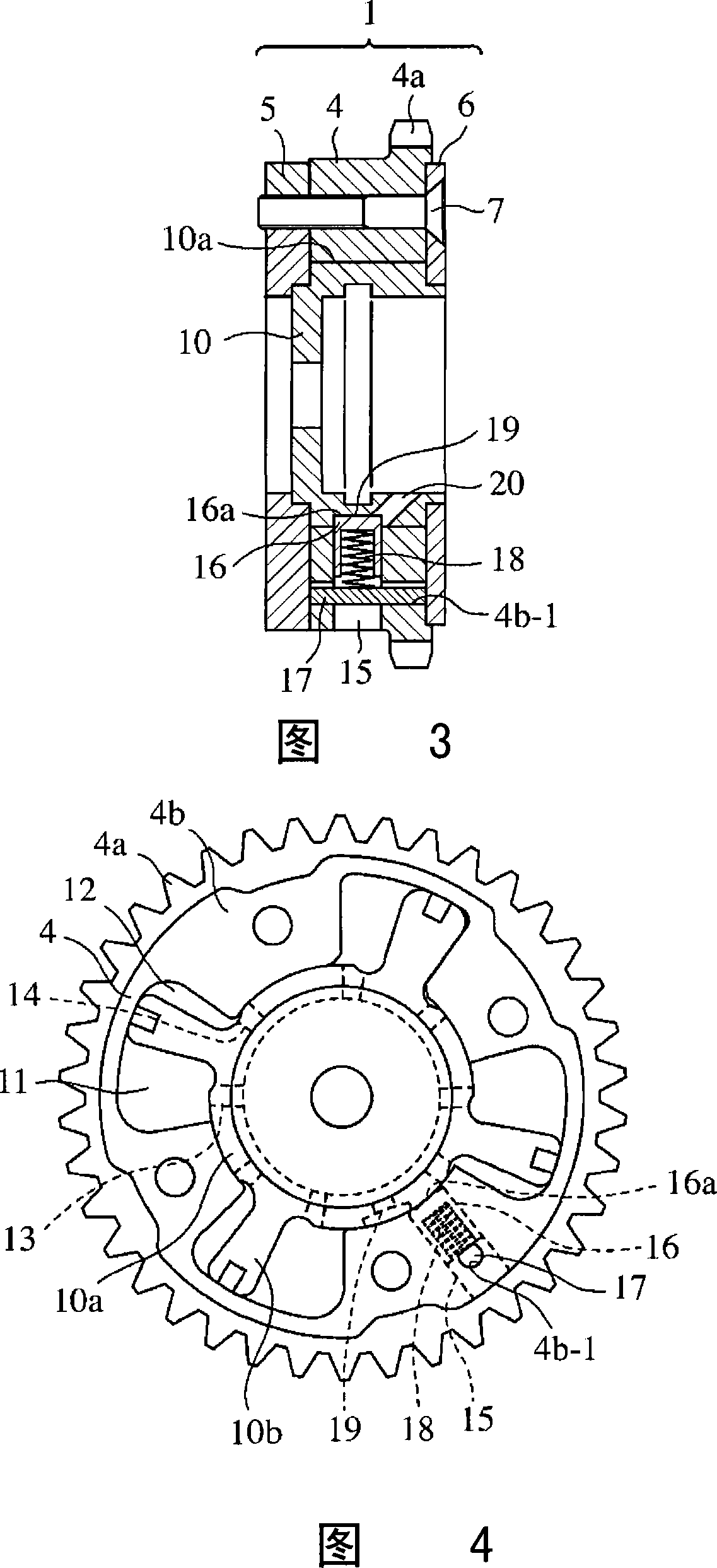
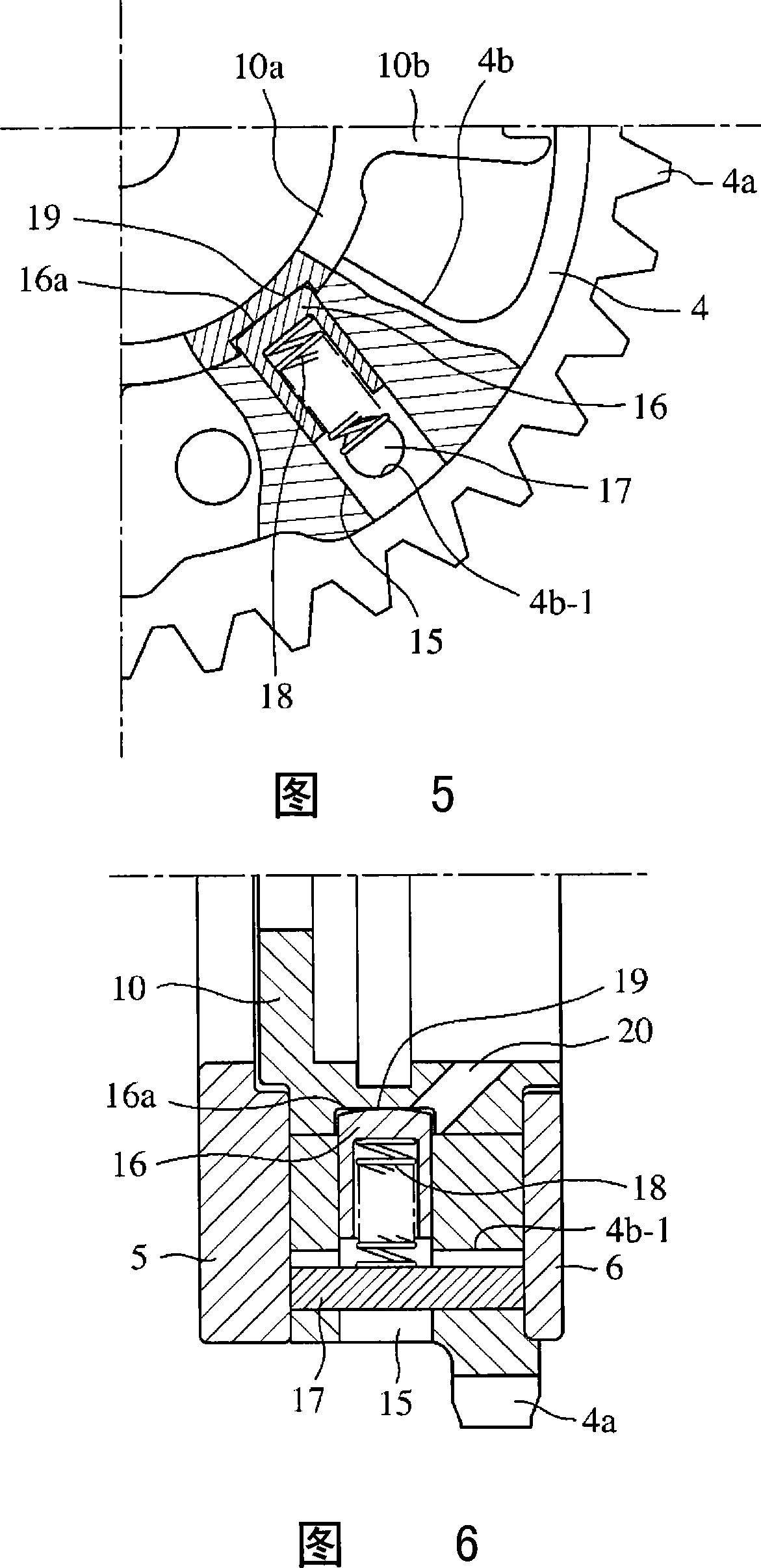
[0029] The accompanying drawings show the internal structure of the valve timing adjustment device according to Embodiment 1 of the present invention. FIG. 1 is a longitudinal sectional view of the valve timing adjustment device when the second rotating body is located at the maximum retardation angle position. FIG. A cross-sectional view along line A-A, Fig. 3 is a longitudinal sectional view along line B-B in Fig. 2, and Fig. 4 is a longitudinal sectional view of the valve timing adjustment device when the second rotating body is at the most advanced angle position.

[0030] As shown in FIGS. 1 to 4 , the valve timing adjustment device 1 according to Embodiment 1 roughly includes: a first valve that rotates synchronously with a crankshaft (not shown) of an engine (not sh...


PUM


Abstract

A valve timing regulation device having a first rotating body co-rotating with a crankshaft; a second rotating body integrally fixed to an intake or exhaust camshaft; a first hole radially penetrating through a shoe formed inside the first rotating body; a second hole formed in the shoe, intersecting with the first hole; a coil spring pressing a lock pin received in the first hole to engage the lock pin with a recess formed in the outer periphery of the second rotating body; and a shaft inserted in the second hole for preventing jumping out of the coil spring.

Description

technical field [0001] The present invention relates to a valve timing regulation device for controlling the opening and closing timing of an intake valve or an exhaust valve of an internal combustion engine (hereinafter referred to as an engine) such as an engine. Background technique [0002] A conventional valve timing adjustment device includes: a first rotating body that has a housing that has a plurality of protrusion-shaped shoes (shoes) inside and that forms a hydraulic chamber between the shoes; The front cover and the rear cover of the oil pressure chamber are fixed integrally and rotate integrally with the crankshaft; The multiple blades of the chamber can rotate relatively at a predetermined angle in the first rotating body, and are integrally fixed with the intake or exhaust camshaft, and supply and discharge oil pressure to the oil pump for supplying oil to the sliding part of the engine, and use this Oil pressure is used to control the relative position of th...

Claims


Application Information

Patent Timeline
Patent Type & Authority Applications(China)
IPC IPC(8): F01L1/34
CPCF01L2001/34473F01L2001/34456Y10T29/49293F01L1/3442
Inventor 弓达孝治坂田晃衣川浩行
Owner MITSUBISHI ELECTRIC CORP
Why Eureka
Try Eureka