
Spark plug

A spark plug and insulator technology, applied in the field of spark plugs, can solve problems such as hindering the reduction of the diameter of spark plugs, unable to meet the reduction of the diameter of engine spark plugs, etc., and achieves the effects of improving reliability, improving vibration resistance, and increasing vibration frequency.

Inactive Publication Date: 2008-08-20
NGK SPARK PLUG CO LTD
View PDF2 Cites 12 Cited by
  • Summary
  • Abstract
  • Description
  • Claims
  • Application Information

AI Technical Summary

Problems solved by technology

[0005] However, in reality, in order to form the above-mentioned large-diameter portion, it will hinder the reduction of the diameter of the spark plug.
Therefore, it cannot meet the requirements of the engine to reduce the diameter of the spark plug.

Method used


Image

  • Spark plug
  • Spark plug
  • Spark plug

Examples


Embodiment Construction

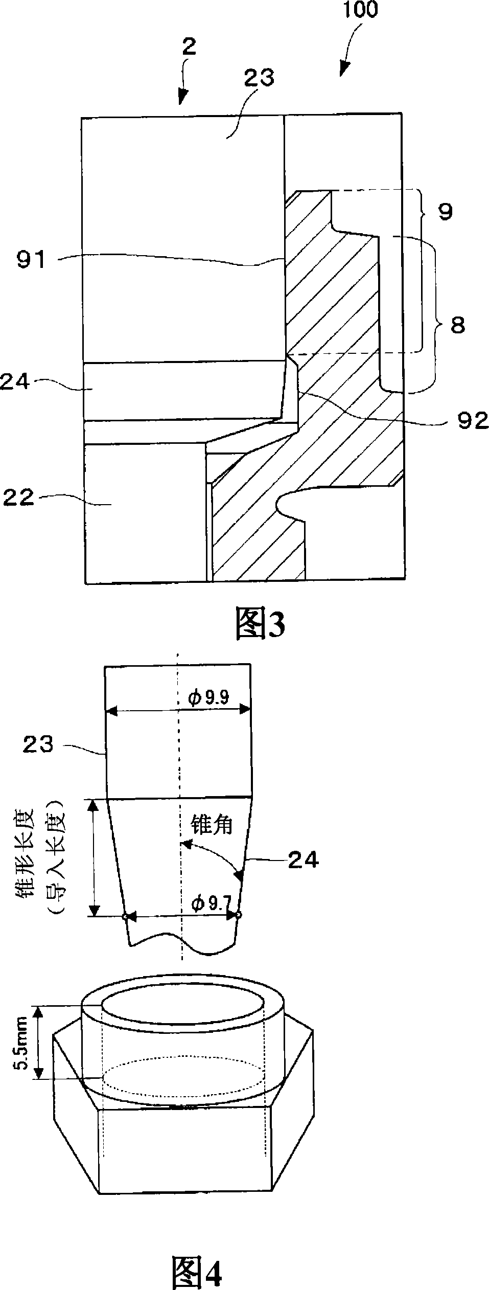
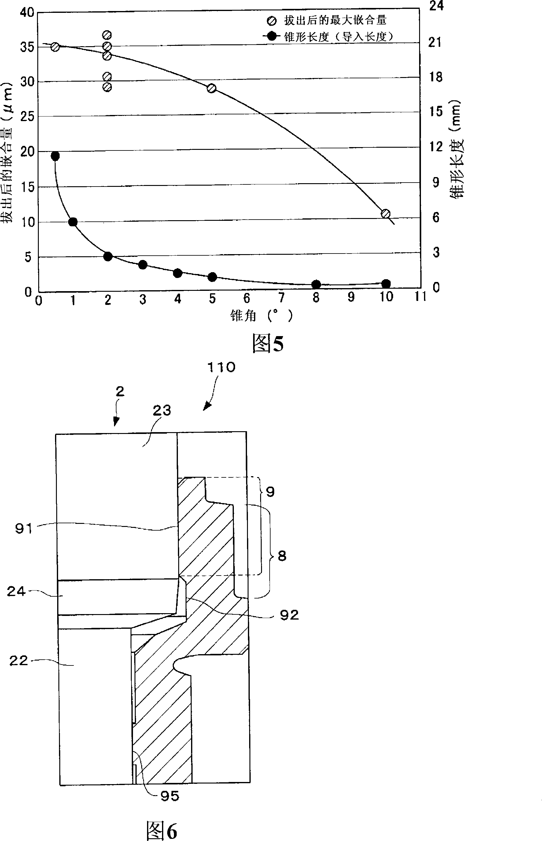
[0105] Embodiments of the present invention will be described below with reference to the drawings. FIG. 1 shows the state before the insulator is attached to the main body partner, and FIG. 2 shows the attached spark plug according to the embodiment of the present invention. The spark plug 100 has a substantially cylindrical metallic shell 1 and a substantially cylindrical insulator 2 in which a front end protrudes and fits into the metallic shell 1 . The center portion inside the insulator 2 is provided with the center electrode 3 along its axial direction, and is formed in a state where the front end portion of the center electrode 3 protrudes from the insulator 2 . Furthermore, a ground electrode 10 is provided facing the front end portion of the center electrode 3 . One end of the ground electrode 10 is combined with the main fitting 1 to form a spark discharge gap with a predetermined interval between the ground electrode 10 and the center electrode 3 .

[0106]The ins...


PUM


Abstract

Disclosed is a spark plug (100) comprising a center electrode (3) extending in the axial direction, a cylindrical insulator (2) holding the center electrode (3), and a cylindrical main metal fixture (1) having an earth electrode (10) at its tip part and having a tool engagement part (8) for fitting to an engine. The main metal fixture (1) comprises a metal fixture side fitting part (9) at a portion thereof on the rear end side more than the tool engagement part (8), and the insulator (2) is radially held by the metal fixture side fitting part (9) in a shrink-fit state.

Description

technical field [0001] The present invention relates to a spark plug used in an internal combustion engine such as an automobile engine. Background technique [0002] A known spark plug has a center electrode, an insulator holding the center electrode, and a metallic shell having a ground electrode at the front end and a tool engaging portion for device installation, and has a structure in which the insulator is supported and fixed in the metallic shell. Such a spark plug generally has a structure in which an insulator is inserted into a cylindrical metallic shell, and one end of the metallic shell is crimped to support and fix the insulator in the metallic shell (for example, refer to Patent Document 1). [0003] The insulator is formed in a cylindrical shape, has a flange-shaped large-diameter portion with the largest outer diameter protruding in the radial direction in the axial direction, and is adjacent to the front end side of the large-diameter portion, and has a smal...

Claims


Application Information

Patent Timeline
Patent Type & Authority Applications(China)
IPC IPC(8): H01T13/36F02P13/00
Inventor 堀田信行小寺英司大林和重杉本典康
Owner NGK SPARK PLUG CO LTD
Learn More