Network interface control program and network interface control device

A technology of network interface and control program, applied in the field of network interface control program and network interface control device, can solve the problem of inability to perform communication obstacle bandwidth change, etc., and achieve the effect of reducing communication bandwidth

Inactive Publication Date: 2008-08-20
FUJITSU LTD
View PDF0 Cites 3 Cited by
  • Summary
  • Abstract
  • Description
  • Claims
  • Application Information

AI Technical Summary

Problems solved by technology

However, this function has the following problem: This function only supports communication failures that can be detected by the LAN switch, such as physical disconnection, and cannot perform flexible bandwidth changes based on temporary communication failures such as traffic increases.

Method used


Image

  • Network interface control program and network interface control device
  • Network interface control program and network interface control device
  • Network interface control program and network interface control device

Examples


no. 1 example

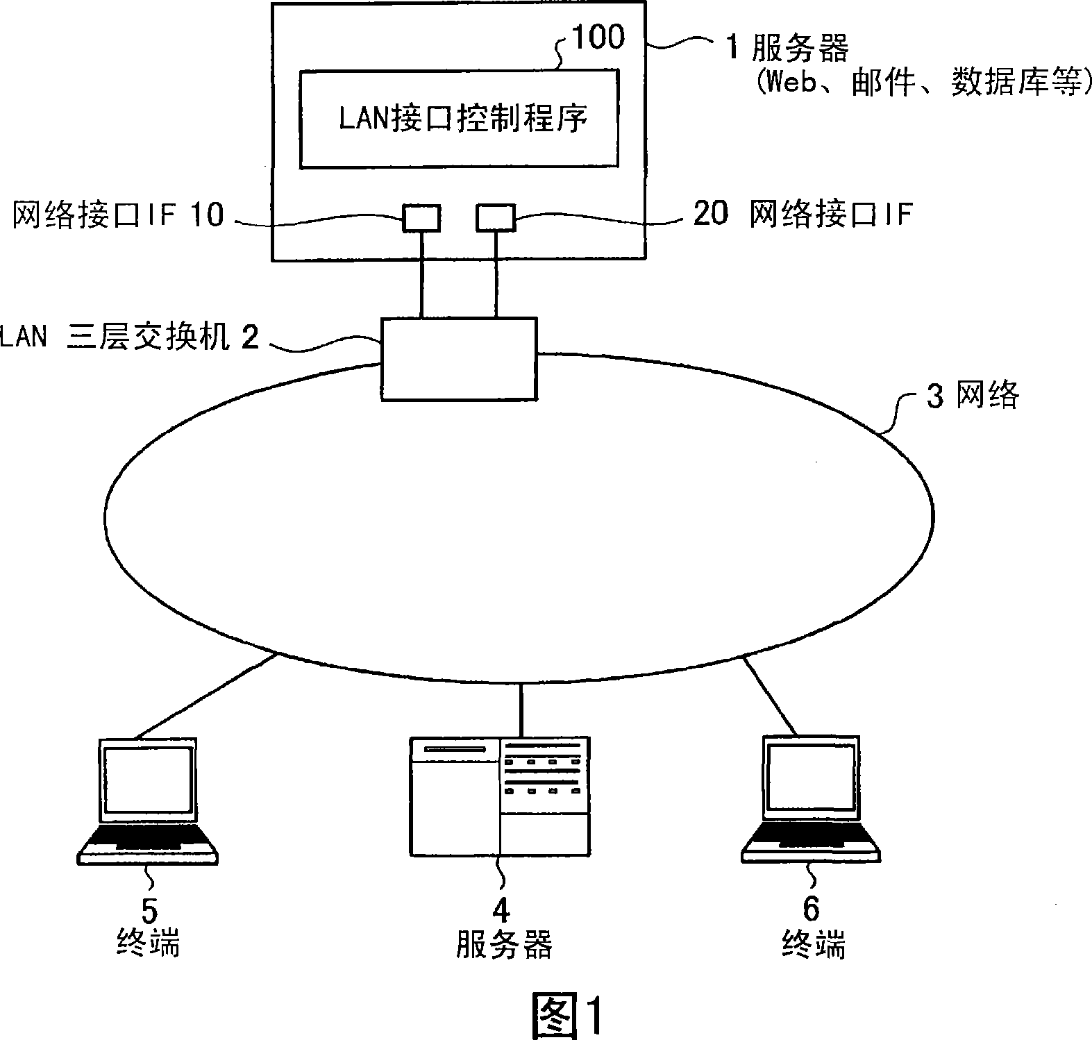
[0066] First, a network structure to which the LAN interface control program of the first embodiment is applied will be described. FIG. 1 is an explanatory diagram for explaining a network configuration to which a LAN interface control program of the first embodiment is applied. As shown in the figure, the server 1 is a computer used as a Web server, a mail server, a database server, and the like. The server 1 is connected to the network 3 via a layer 3 switch (L3 Switch), and performs data transmission and reception with other servers 4 and terminals 5 and 6 connected to the network 3 and connected to the network 3 .

[0067] In addition, this server 1 has two network IF10,20. The network IFs 10 and 20 are connected to the LAN layer 3 switch 2 through respective transmission lines, and are connected to the network 3 via the LAN layer 3 switch 2 .

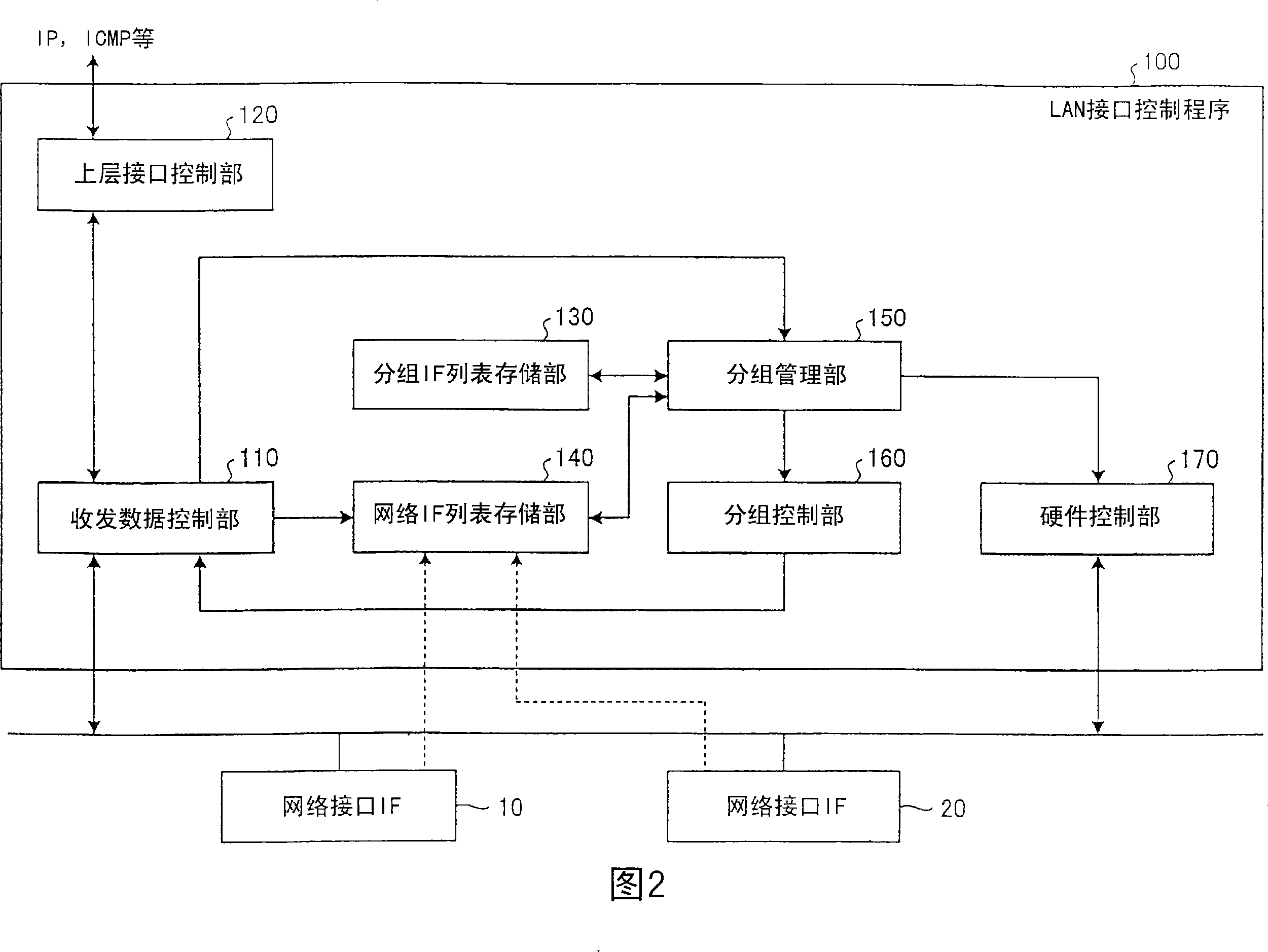
[0068] The LAN interface control program 100 of the first embodiment is executed on the server 1, and functions as a device dri...

no. 2 example

[0101] In the second embodiment, the bandwidth control according to service priority when multiple services are simultaneously processed on the server will be described. 7-1 and 7-2 are diagrams illustrating the operation of the LAN interface control program 100 of the second embodiment. The difference between the LAN interface control program 100 of the second embodiment and the first embodiment is that the group IF list also has service priority-related settings. In addition, in this second embodiment, although the case where the server 1 has three network IFs is described, the number of network IFs is not limited to three, as long as it is three or more.

[0102] As shown in FIG. 7-1(a), data transmission and reception related to the two services A and B executed in the server 1 are distributed to the respective network IFs 10 to 30 by the LAN interface control program 100 for execution. Each of the network IFs 10 to 30 is connected to the network via the LAN layer 3 switc...


PUM


Abstract

In a network interface control program (100) executed on a computer (1) having a plurality of network interfaces (10, 20) connected to a network repeater (2), when a traffic increase-detecting means (150) detects an increase of the traffic of the network interface (10), a band-expanding means (160) groups the network interface (10) and the other unused network interface (20) together. In this manner, the communication band can be expanded.

Description

technical field [0001] The present invention relates to a network interface control program and a network interface control device for controlling a plurality of network interfaces connected to a network relay device, and particularly relates to a method of automatically performing bandwidth expansion / reduction according to communication conditions, thereby making it variable A network interface control program and a network interface control device for an appropriate communication bandwidth. Background technique [0002] Conventionally, in communication via a network interface (network IF), bandwidth expansion / reduction processing has been manually performed. For example, when a communication failure such as a communication response delay occurs in the server due to an increase in communication traffic, as a countermeasure, the cause is manually determined based on statistics such as CPU load and data transfer volume, and the cause is manually resolved. Perform operations ...

Claims


Application Information

Patent Timeline
Patent Type & Authority Applications(China)
IPC IPC(8): H04L12/44
CPCY02B60/33H04L45/245H04L47/11H04L47/10H04L47/125Y02D30/50
Inventor 阿部友明
Owner FUJITSU LTD
Why Eureka
Try Eureka