Electrical pressure cooker

A technology of electric pressure cooker and pot cover, which is applied in the direction of pressure cooker, etc. It can solve the problems of inability to release pressure, delay of temperature signal, easy blockage of exhaust port, etc., achieve safe and reliable pressure release, avoid blockage of exhaust valve, and simple structure

Active Publication Date: 2010-06-02
MIDEA GRP CO LTD
View PDF8 Cites 0 Cited by
  • Summary
  • Abstract
  • Description
  • Claims
  • Application Information

AI Technical Summary

Problems solved by technology

The temperature signal obtained by the electric pressure cooker with this structure has a large delay compared with the pressure value in the cooker, resulting in inaccurate control
Moreover, the small exhaust port is easy to block, and the pressure cannot be released after the blockage, which poses a serious safety hazard

Method used


Image

  • Electrical pressure cooker
  • Electrical pressure cooker
  • Electrical pressure cooker

Examples


Embodiment 1

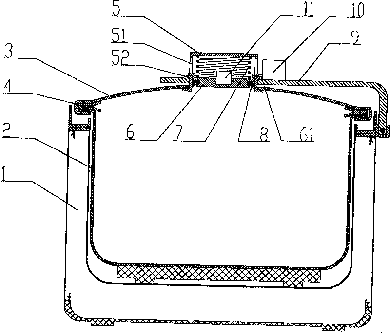
[0034] as attached figure 1 As shown, the pressure cooker of the present invention includes a pot body 1, an inner pot 2 disposed in the pot body 1, a pot cover 3 that can rotate around the center of the inner pot 2, a sealing ring 4 is arranged between the inner pot 3 and the pot cover 2, and the pot The cover 3 is buckled on the inner pot 2, and an electric pressure cooker control circuit (not shown in the figure) is arranged between the pot body 1 and the inner pot 2. Since the improvement of the present invention mainly lies in the pot cover part, other parts will not be described in detail.

[0035] In the present invention, a sliding box 5 is fixed at the center of the pot cover 3. The bottom of the sliding box 5 is open and communicated with the inside of the inner pot 2. The sliding box 5 is usually made into a cylindrical thin-walled cavity. Left and right two vent windows 51, the lower part of the cavity is provided with a sliding block 6 that can slide up and down ...

Embodiment 2

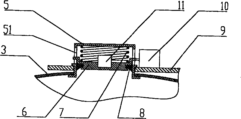
[0043] The difference between embodiment 2 and embodiment 1 is that the switch 10 is installed on the top of the sliding box 5 (it can also be arranged on the side wall of the sliding box 5, but the air leakage window 51 needs to be avoided). as attached Figure 5 As shown, in this installation method, only the shape of the driving lever 61 needs to be changed. Since the pot cover 3 and the sliding box 5 will rotate relative to the lid handle 9, it is better to install the switch 10 on the sliding box 5 than in the first embodiment with the switch 10 installed on the lid handle 9.

Embodiment 3

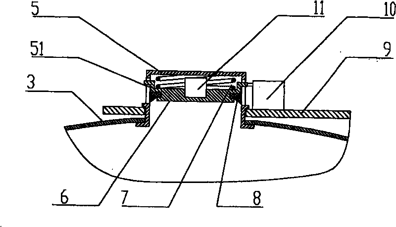
[0045] as attached Figure 6 As shown, the difference between embodiment 3 and embodiment 1 is that the switch 10 is installed on the pot cover 3 .


PUM


Abstract

The invention discloses an electric pressure cooker, particularly to an electric pressure cooker capable of receiving pressure or temperature signal on cooker cover and realizing pressure relief. Theelectric pressure cooker comprises a cooker body, an inner cooker arranged inside the cooker body, a cooker cover capable of rotating around the central axis of the inner cooker, and a control circuitarranged between the cooker body and the inner cooker, wherein a cooker cover is provided thereon with a cavity that is communicated with the inner cooker, a sliding block movably connected with theinner cooker and capable of sliding upwardly and downwardly inside the electric pressure cooker is arranged in the lower part of the cavity, a dynamically sealed element contacting with the inner wallof the cavity is arranged on the sliding block, and an elastic element is arranged between the upper part of the sliding block and the top wall of the cavity; a switch triggered by the sliding of thesliding block is arranged inside or outside the cavity, and / or a temperature sensor is installed on the sliding block, and the switch and / or temperature sensor are connected with the control circuit.The inventive electric pressure cooker can accurately receive signal of the pressure or temperature inside the cooker and realize rapid pressure relief. The inventive electric pressure cooker has theadvantages of smart design, simple structure, and low production cost.

Description

Technical field: [0001] The invention relates to an electric pressure cooker, in particular to an electric pressure cooker capable of obtaining pressure or temperature signals on the cover of the pot and realizing pressure release, and is an improved technology of the electric pressure cooker. Background technique: [0002] The existing electric pressure cooker has two structures: one is that the lid of the pot is fastened with the outer pot. When there is pressure in the pot, the inner pot moves down, and the pressure switch is turned on and off by the displacement difference of the compound motion of the outer pot and the pressure switch. , to achieve the purpose of the work. When the abnormal situation makes the pressure too high, the pressure will be released through the large gap between the inner pot, the sealing ring and the pot cover. However, the displacement difference is difficult to control, and the deformation is different every time, so the pressure is unstabl...

Claims


Application Information

Patent Timeline
Patent Type & Authority Patents(China)
IPC IPC(8): A47J27/09A47J27/08
Inventor 陈淦林
Owner MIDEA GRP CO LTD
Why Eureka
Try Eureka