Molding type diaphragm filtering plate and molding method

A diaphragm filter plate, compression molding technology, applied in separation methods, chemical instruments and methods, filtration separation, etc., can solve problems such as shortened life, fracture of the diaphragm filter plate core, and insufficient diaphragm density to achieve increased service life , Reliable sealing performance, good effect on tympanic membrane

Active Publication Date: 2008-08-27
HANGZHOU XINGYUAN FILTER TECH
View PDF2 Cites 15 Cited by
  • Summary
  • Abstract
  • Description
  • Claims
  • Application Information

AI Technical Summary

Problems solved by technology

Although the above two patents have made detailed descriptions on the structure and manufacturing process of the filter plate core and the diaphragm, as well as the assembly structure and assembly process between the diaphragm and the filter plate core, the cooperation between the filter plate core and the embedded diaphragm must be Use CNC machine tools to process slots and chamfers; second, the assembly size between the diaphragm and the filter plate core requires high precision, high processing costs, and time-consuming labor. Even so, when the diaphragm and the filter plate core are assembled, due to other Influenced by many factors such as material, temperature, process, and processing accuracy, it is difficult to achieve precise assembly between the diaphragm and the filter plate core, which directly affects the quality stability of the product; third, in addition to the injection-molded diaphragm, the existing d

Method used


Image

  • Molding type diaphragm filtering plate and molding method

Examples


Embodiment 1

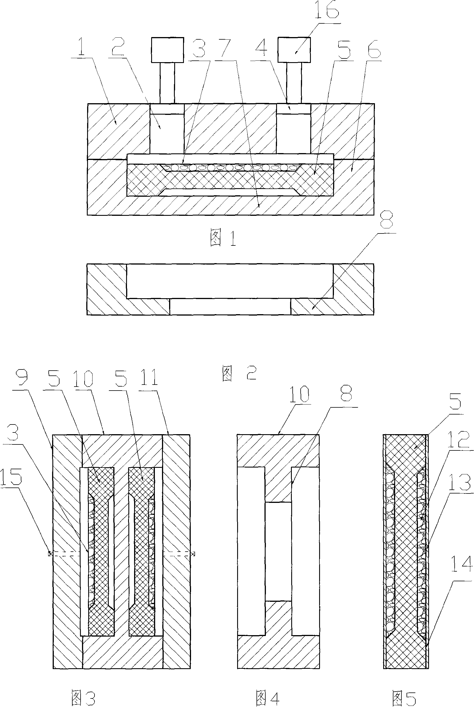
[0015] Embodiment 1: with reference to accompanying drawing 1~2. Molded diaphragm filter plate molding die, it comprises upper mold 1 and lower mold 6, and lower mold 6 is frame structure, and its manufacturing technology and craft are prior art, do not make description here. Filter plate core 5 is positioned at the mold frame of lower mold 6 and can take out, and the bottom of lower mold 6 molds is positioning boss 8 or bottom frame 7, and its manufacturing technology and technology are prior art, do not narrate here. The face of the filter plate core 5 is the die face of the lower die 6, that is to say, the face of the filter plate core 5 is used as the die face of the lower die 5, and the die cavity 3 of the upper die 1 is the diaphragm forming cavity. The upper mold 1 is provided with one or two or more feeding ports 2, and an extrusion plate 4 matching the feeding port is arranged in the feeding port, and two or more extrusion plates 4 are under the action of the extrusio...

Embodiment 2

[0016] Embodiment 2: on the basis of embodiment 1, feed inlet is not established on the patrix 1 and adopt extruding equipment (mechanism), as oil press or hydraulic press directly patrix and counterdie are clamped, thereby will be positioned at the mold cavity The plasticized (molten) plastic is extruded into various parts of the cavity.

Embodiment 3

[0017] Embodiment 3: on the basis of embodiment 1 or 2, or on the basis of 1 and 2, the molding method of molded diaphragm filter plate, it comprises filter plate core, and filter plate core is put into lower mold frame, and filter plate The tympanic surface of the core is equipped with a degradable mold core, put the plasticized plastic group on the tympanic surface of the filter plate core, then close the upper mold and the lower mold frame, and form an integrated single-sided plastic diaphragm after cooling Then turn the single-sided filter plate into the lower mold frame, place a degradable mold core on the tympanic surface of the filter plate core, and put the plasticized plastic group on the tympanic surface of the filter plate core , the upper mold and the lower mold frame are molded together, and an integrated double-sided plastic diaphragm filter plate core is formed after cooling; or the filter plate core is placed in the lower mold frame, and the tympanic membrane su...


PUM


Abstract

The invention relates to a structure and a molding method for directly molding a diaphragm on the core face of a filter plate. The structure comprises a filter plate core; the filer plate core is disposed in a lower mold frame; a decomposable mold core is arranged on the diaphragm face of the filter plate core; then a plasticized plastic lump is disposed on the diaphragm; an upper mold frame and the lower mold frame are combined and cooled to form an integrated single-surface plastic diaphragm filter plate; then the single-surface filter plate is turned over and disposed in the lower mold frame; the disposable mold core is arranged on the diaphragm face of the filter plate core; the plasticized plastic lump is then placed on the diaphragm face; the upper mold frame and the lower mold frame are then combined and cooled to form an integrated double-surface plastic diaphragm filter plate core.

Description

technical field [0001] The invention relates to a structure and a molding method for directly molding a diaphragm on the core surface of a filter plate, belonging to the field of diaphragm filter plate manufacturing. Background technique [0002] 1. Injection molding process of filter plate core: the patent number is 200410037113.5, the name is "new plastic filter plate core or plate forming process", the new plastic filter plate core or plate forming process, hot runner plastic filter plate core forming mold or hot runner plate The hot runner opening of the forming mold is located on the upper or bottom or side of the hot runner plastic filter plate core forming mold or the hot runner plate forming mold. The outlet of the injection molding mechanism of the injection molding machine is aligned with the hot runner opening, and the plastic raw material is heated and plasticized by the injection molding mechanism. Finally, the discharge port is injected into the cavity of the m...

Claims


Application Information

Patent Timeline
IPC IPC(8): B29C43/36B29C43/18B29C33/52B01D25/168
Inventor 周立武
Owner HANGZHOU XINGYUAN FILTER TECH
Why Eureka
Try Eureka