Tidal generating equipment as well as generating method thereof

A technology of tidal power generation and facilities, applied in tidal flow/damless hydropower, hydropower, hydropower stations, etc., can solve the problems of complex design and construction, unreasonable design, high construction cost, etc., and achieve high work efficiency, reasonable structure, The effect of reducing input costs

Inactive Publication Date: 2008-08-27
何煌清
View PDF0 Cites 21 Cited by
  • Summary
  • Abstract
  • Description
  • Claims
  • Application Information

AI Technical Summary

Problems solved by technology

[0002] The existing tidal power generation method is mainly to build dams in harbors, intercept seawater, form tidal reservoirs, install hydroelectric generator sets, and rely on the water level difference formed between rising and falling tides and reservoirs to generate electricity. Due to the complex design and construction, it is necessary to install water turbines on the inlet and outlet channels and outlet channels, or to build multiple pools for adjustment, which makes the construction cost very high, and the design is unreasonable, the work efficiency is low, and it is difficult to meet the development needs.

Method used


Image

  • Tidal generating equipment as well as generating method thereof
  • Tidal generating equipment as well as generating method thereof
  • Tidal generating equipment as well as generating method thereof

Examples


Embodiment Construction

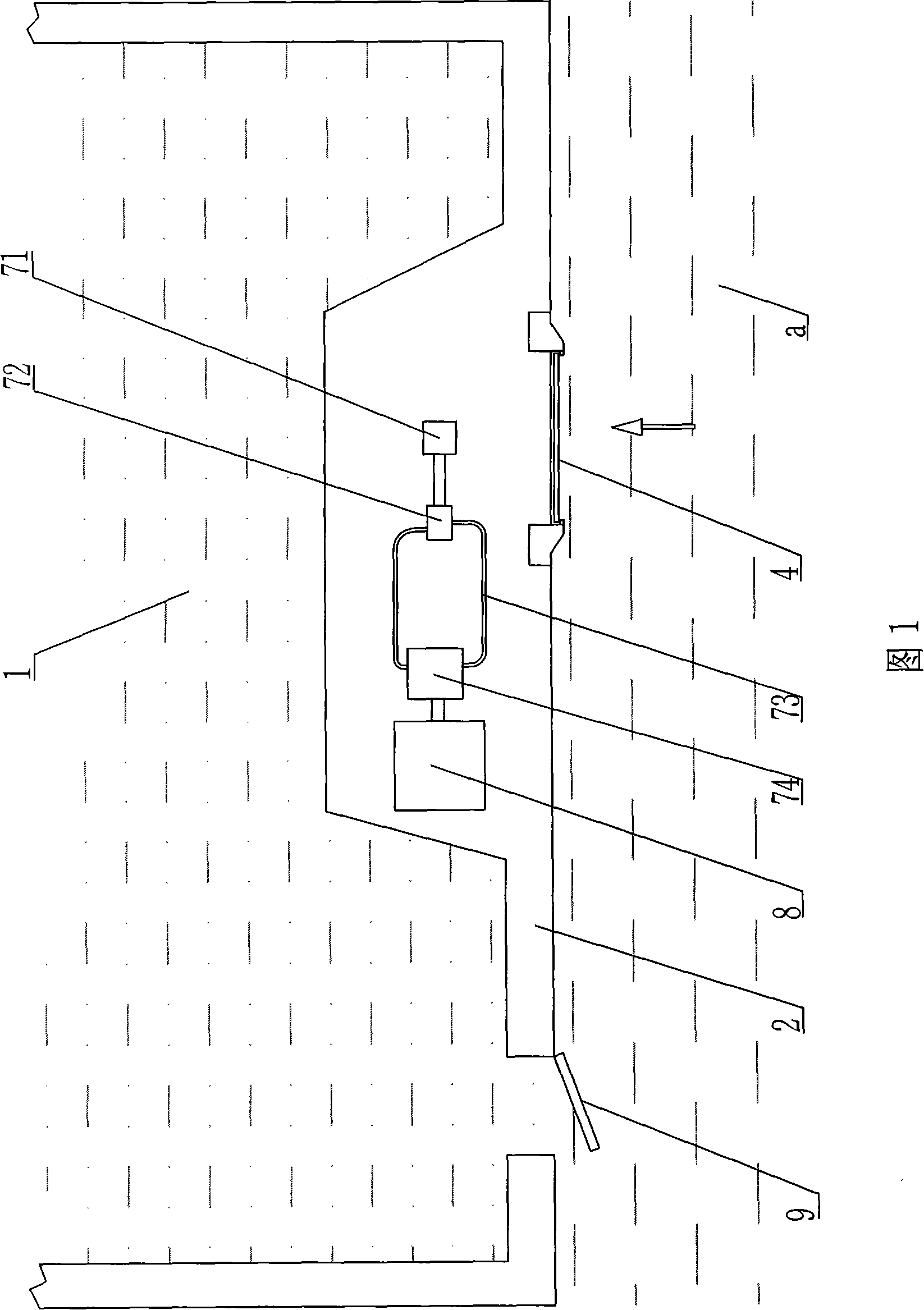
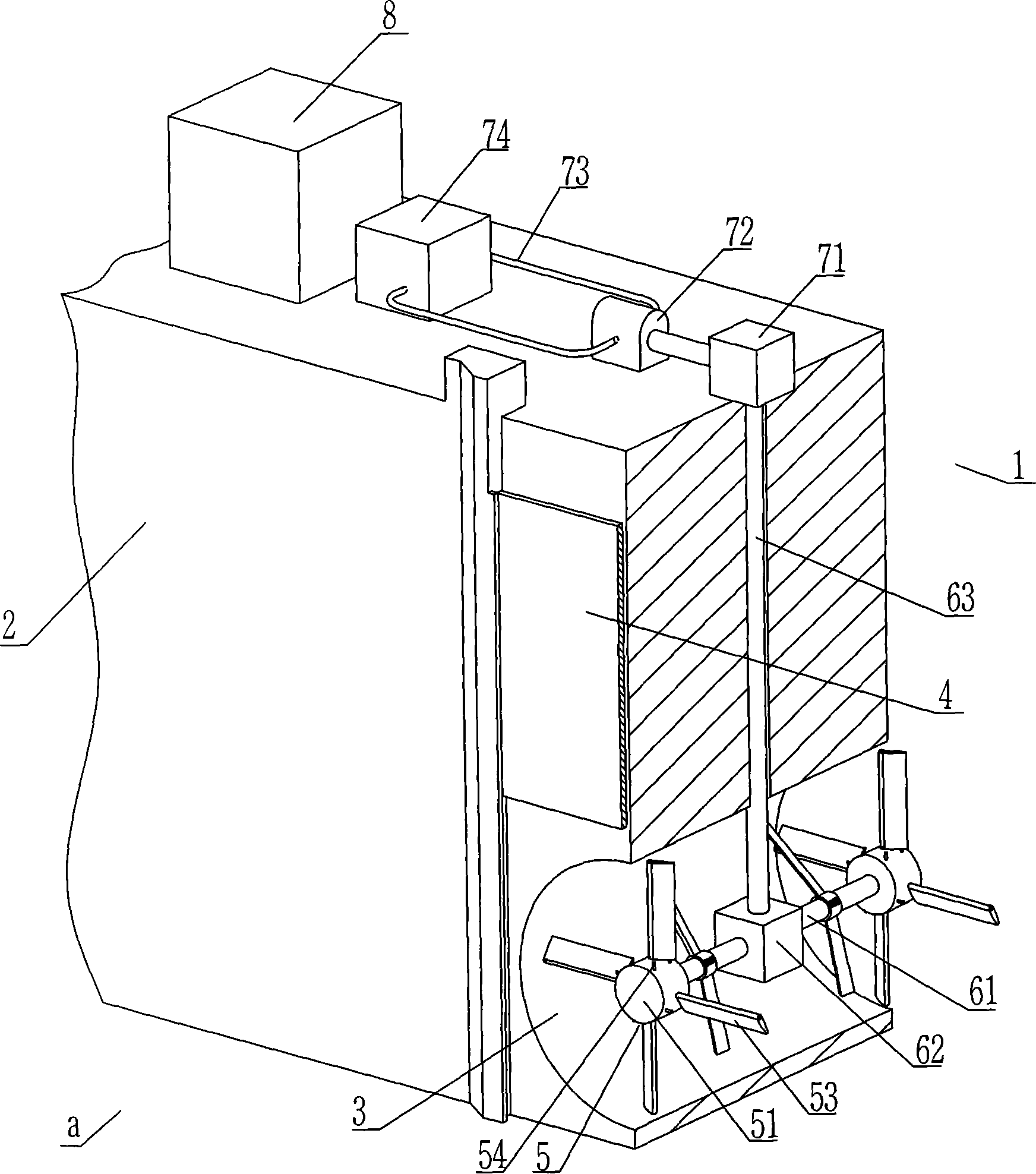
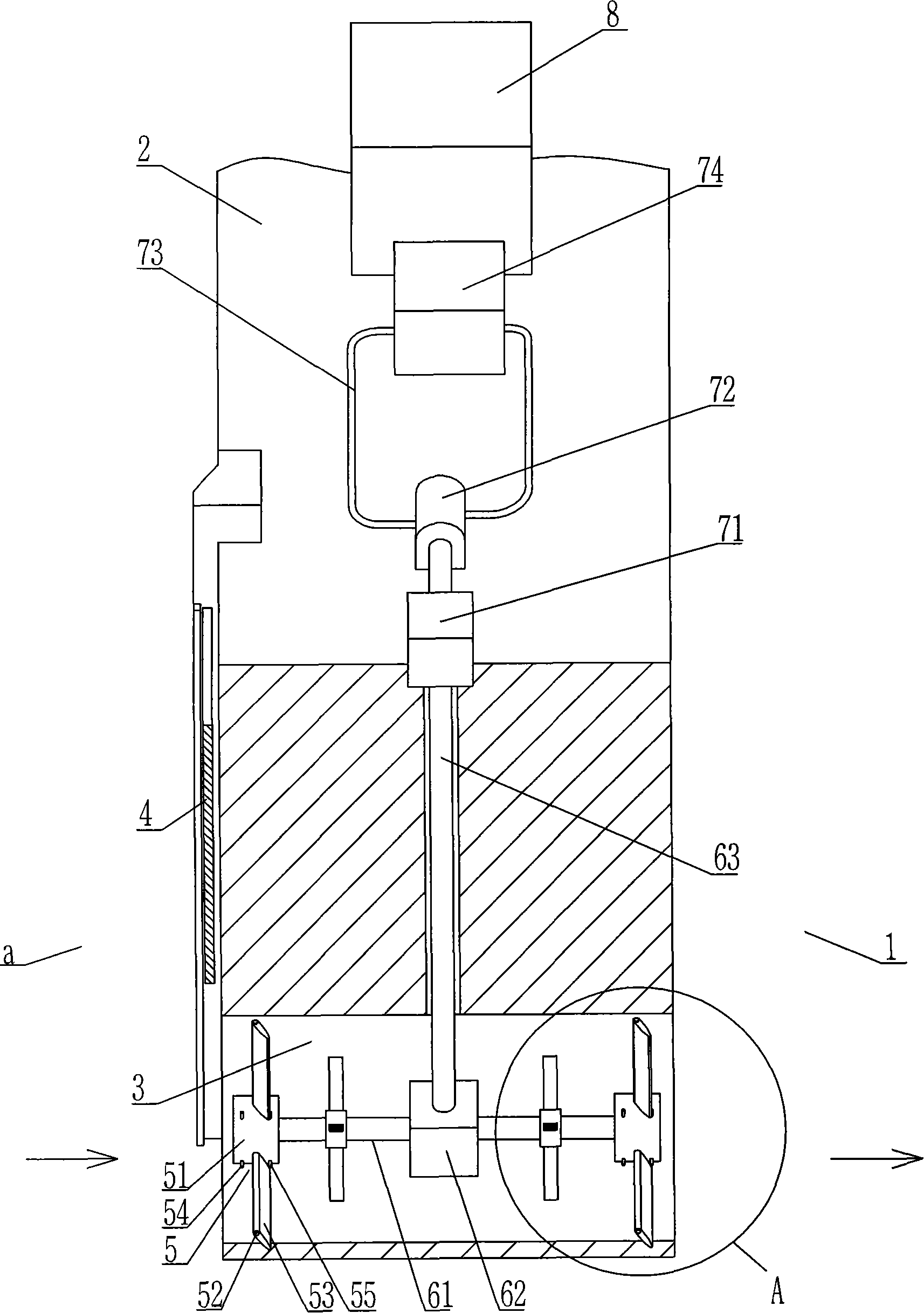
[0025] Refer to Figure 1 to Figure 5 , a tidal power generation facility, first choose a coastal location with a large tidal drop, artificially build a reservoir 1 near the sea, and set a culvert 3 under the dam 2 on the side of the reservoir 1 near the sea to connect to the outside of the pond a , the location of the culvert 3 is located at the lowest position when the tide is ebbing. Since the tide has certain dynamics, the lowest or highest position described in the present invention can also be an approximate value. The culvert 3 is equipped with a regulating gate 4 and a water wheel 5. The water Wheel 5 comprises bearing 51, and bearing 51 is provided with strut 52 radially, and strut 52 is sleeved with blade 53 that can swing around it, and bearing 51 is provided with the positioning device that can limit the swing angle of blade 53, and bearing 51 Installed on the end of a rotating shaft 61, the rotating shaft 61 drives the vertical shaft 63 through the steering gear b...


PUM


Abstract

The invention relates to a tide generating facility and a generating method thereof, which include as follows: a culvert is arranged under a seaside dyke of a coastal impounding reservoir; a regulating gate and a water wheel are arranged in the culvert; the water wheel comprises a support saddle; a mainstay is arranged on the support saddle in radial direction; the mainstay is sleeved with vanes which are capable of swaying around the mainstay; a positioning device for restricting sway angles of the vanes is arranged at the support saddle; a vertical shaft is driven by a rotating shaft through a steering gear box; and a power conveying system is connected to the top of the vertical shaft, and the generator is driven by the power conveying system. Before a tide rises, the regulating gate is closed. During the process of tide rising, when the water level outside the pool rises to a certain position, the regulating gate is opened. The water outside flows into the pool and at the same time the water wheel is driven by the flowing water to rotate and generate electricity. Before a tide falls, the regulating gate is closed at first. When the external water level falls to a certain position, the regulating gate is opened and the water flows out and shocks the vanes of the water wheel. The vanes are changed to another angle and rotate in the same direction. The tide generating facility is efficient in operation.

Description

technical field [0001] The invention relates to a power generation device, in particular to a power generation facility using tidal energy to generate electricity and a power generation method applied to the facility. Background technique [0002] The existing tidal power generation method is mainly to build dams in harbors, intercept seawater, form tidal reservoirs, install hydroelectric generator sets, and rely on the water level difference formed between rising and falling tides and reservoirs to generate electricity. Due to the complex design and construction, it is necessary to install water turbines on the inlet and outlet channels and outlet channels, or to build multiple pools for adjustment, which makes the construction cost very high, and the design is unreasonable, and the work efficiency is low, so it is difficult to meet the development needs. Contents of the invention [0003] In order to overcome the deficiencies of the prior art, the present invention provi...

Claims


Application Information

Patent Timeline
Patent Type & Authority Applications(China)
IPC IPC(8): F03B13/26E02B9/00
CPCY02E10/22Y02E10/28Y02E10/20Y02E10/30
Inventor 何煌清
Owner 何煌清
Why Eureka
Try Eureka