Method for detecting hub installing hole shape-location parameter based on picture recognition

A detection method and image recognition technology, applied in image data processing, image enhancement, character and pattern recognition, etc., can solve the problems of single function, expensive equipment, lack of automatic data processing ability, etc., to reduce labor intensity and efficiency. and the effect of improving accuracy

Inactive Publication Date: 2008-08-27
ZHEJIANG UNIV
1 Cites 47 Cited by

AI-Extracted Technical Summary

Problems solved by technology

Domestic wheel hub factories generally use three-coordinate measuring machines to measure the diameter of hub bolt holes, the distance between adjacent bolt holes and other parameters, but the expensive price of this equipment and the high requirements for operators and the environment make it difficult to popularize
On ...

Method used

[0027] The lower end surface of the base 1 is provided with several balance feet, at...

Abstract

The invention discloses a hub form-position parameter detection method based on image recognition which comprises the following steps: a digital image of a hub with a calibration template is taken, and the distortion correction coefficient of the digital image is obtained; the digital image of the hub is orderly made grey conversion, image compression and image binarization processing; the binarized image is made an area partition based on the connected area lookup to obtain the effective area of each mounting hole of the hub; the effective area of each mounting hole of the hub is made an edge detection to extract the edge information of the mounting hole to locate the boundary of the mounting hole, meanwhile the boundary of the mounting hole is made a geometric distortion correction; random points on the boundary of the mounting hole is made a sub-pixel interpolatory subdivision to obtain the more accurate boundary of the mounting hole; the circle center and the diameter of each mounting hole are fit according to the random points of the boundary of the mounting hole, and a pitch circle parameter of the hub is fit according to the circle center position of each bolt hole. The method of the invention ensures that the efficiency and the accuracy of the hub detection process are greatly improved and also alleviates the labor intensity of the workers.

Application Domain

Technology Topic

Image

  • Method for detecting hub installing hole shape-location parameter based on picture recognition

Examples

  • Experimental program(1)

Example Embodiment

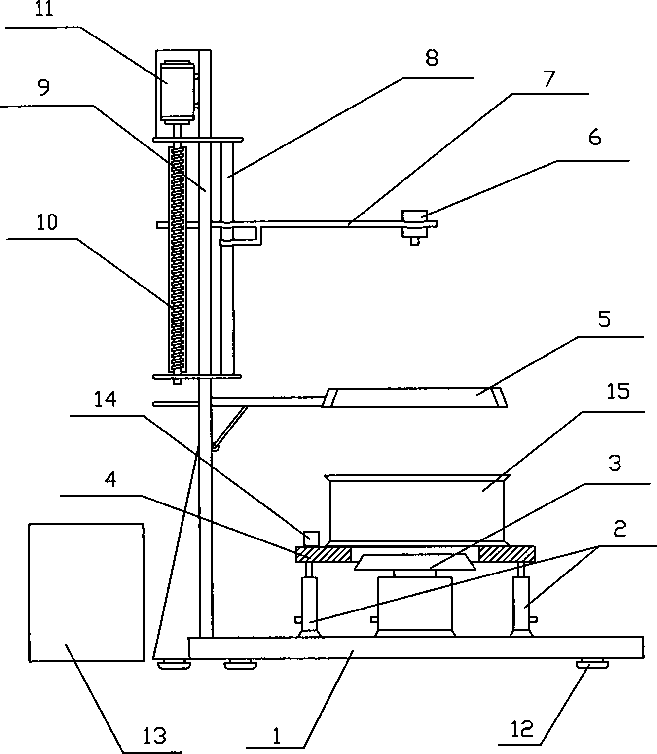
[0026] Such as figure 1 As shown, a vehicle hub detection device includes a base 1. A hub tray 4 with a lifting mechanism and a clamp 3 are provided on the base 1. The lifting mechanism is a cylinder 2, at least two cylinders 2, and one end of the cylinder 2 is vertical It is fixed on the base 1, and the other end is fixed perpendicularly to the lower end surface of the hub tray 4 so that the hub tray is parallel to the horizontal plane.
[0027] The lower end surface of the base 1 is provided with several balance feet, at least 3 balance feet, which is convenient for the stable placement of the detection device.
[0028] The hub tray 4 is arranged with the clamp 3 as the center, and a positioning block 14 with an adjustable distance is provided on the hub tray 4 for pre-positioning the hub during detection.
[0029] One end of the clamp 3 is vertically fixed on the base 1, and the other end is a truncated cone. The cone is equipped with a multi-jaw telescopic mechanism. The top is equipped with a pneumatic clamping piece, and the lower part is matched with the top pneumatic clamping piece to clamp or Loosen the center hole of the hub.
[0030] The base 1 is provided with a top beam 9 vertically fixed to the base 1. The top beam 9 is fixed with a ring light source 5 through a connecting rod. The ring light source 5 is located directly above the fixture 3. The ring light source 5 uses carefully selected LED lights to emit uniform light. .
[0031] The upper part of the top beam 9 is provided with a motor 11, the top beam 9 below the motor 11 is fixed with a vertical screw 10 and a sliding rod 8, and the lower part of the motor 11 is connected with the screw 10, and the sliding rod 8 is covered with a horizontal beam 7. One end of the beam 7 is provided with a screw hole, and the screw rod 10 passes through the screw hole and drives the beam 7 to move up and down.
[0032] A camera 6 (Hangzhou Aotai Image System Integration Co., Ltd. AT-MVC3000) is fixed at the other end of the beam 7, and the camera 6 is located directly above the ring light source 6. When the motor 11 works, the screw rod 10 is driven to rotate, so that the screw rod 10 drives one end of the cross beam 7 and the cross beam 7 moves up and down along the sliding rod 8 to adjust the height of the camera 6.
[0033] The camera 6 is connected to a data controller 13 through a data cable, and the data controller 13 is mainly used to analyze and process the data collected by the camera 6.
[0034] The working process of the vehicle hub detection device of the above embodiment is as follows:
[0035] 1. Turn on the power and start the hub detection device.
[0036] 2. Before testing a certain type of aluminum alloy wheel hub, calibrate the type of wheel hub first. The specific calibration steps are as follows:
[0037] a) Fix the checkerboard calibration template tightly on the lower end surface of the central mounting hole of the calibration hub, and place the hub with the calibration template horizontally on the hub tray 4 of the detection device, and the outer circumference of the hub is close to the positioning block 14 with adjustable distance On, complete pre-positioning;
[0038] b) The hub is lowered by the lifting mechanism, the center hole of the hub is infinitely close to the fixture 3, and the truncated cone on the top of the fixture 3 guides the aluminum alloy hub to complete the precise positioning on the detection device, and then clamp the aluminum to be measured with a pneumatic clamping piece Alloy wheels;
[0039] c) The camera 6 is driven by the motor 11 to continuously adjust the height to obtain the best and clear imaging image of the hub mounting hole and then shoot, and obtain the digital image of the hub with the calibration template in the center area;
[0040] d) The operator issues a "calibration calculation" instruction through the data controller 13, extracts the sub-pixel corner coordinates of the calibration template in the digital image through the corner detection method based on the improved Harris algorithm, and calibrates the principal point of the digital image coordinate system and CMOS The pixel pitch is calculated according to the principal point position and the CMOS pixel pitch to obtain the distortion correction coefficient of the digital image.
[0041] 3. After the calibration is completed, the detection device enters the waiting state. After the aluminum alloy hub 15 to be tested is off the assembly line, it is placed horizontally on the hub tray 4 of the detection device, and the outer circumference of the hub is close to the positioning block 14 with adjustable distance , Complete pre-positioning;
[0042]4. The operator sends an instruction through the data controller 13 to select two different detection modes, "automatic" and "manual". The method for detecting the shape and position of the wheel hub mounting hole parameters is as follows:
[0043] (1) The operator sends a "start measurement" command through the data controller 13, the lifting mechanism lowers the hub, and the center hole of the hub is infinitely close to the fixture 3, and the truncated cone on the top of the fixture 3 guides the aluminum alloy hub to complete the inspection on the testing device. Precise positioning, and then clamp the tested aluminum alloy wheel with pneumatic clamping parts, and the camera 6 takes a 24-bit color bitmap of the wheel on the side where the mounting hole of the tested wheel is located;
[0044] (2) The captured 24-bit color bitmap of the wheel is sequentially subjected to gray-scale conversion and image compression based on the standard brightness conversion formula Y=0.299R+0.587G+0.114B (compression ratio 1:1024 to 1:2048.) And image binarization processing;
[0045] (3) The binarized image is segmented based on the connected area search to obtain the effective area of ​​each mounting hole of the wheel hub;
[0046] (4) Perform edge detection on the effective area of ​​each mounting hole of the hub, use 3*3 non-linear median filter and improved eight-direction Sobel gradient algorithm to extract the edge information of the mounting hole image, and locate the boundary of the mounting hole;
[0047] (5) Perform polynomial-based sub-pixel interpolation for random points on the boundary of the mounting hole to obtain a more accurate boundary, and at the same time perform geometric distortion correction on the boundary of the mounting hole according to the distortion correction coefficient;
[0048] (7) According to the random points on the boundary of the mounting hole, use the least square method to fit the center and diameter of each mounting hole, and then further fit the pitch circle parameters of the hub according to the center position of each bolt hole. According to the calibrated CMOS pixel pitch, the hub parameter is converted from the pixel unit in the image coordinate system to the millimeter unit in the physical coordinate system.
[0049] 5. After the inspection is completed, remove the aluminum alloy wheel 15 from the wheel tray 4 and prepare to inspect the next aluminum alloy wheel of the same model;
[0050] 6. After all the wheels of the same model have been inspected, the operator sends an "inspection end" command through the data controller 13 to drive the motor 11 to adjust the height and reset the position of the camera 6;
[0051] 7. Turn off the hub detection device and cut off the power supply.

PUM

no PUM

Description & Claims & Application Information

We can also present the details of the Description, Claims and Application information to help users get a comprehensive understanding of the technical details of the patent, such as background art, summary of invention, brief description of drawings, description of embodiments, and other original content. On the other hand, users can also determine the specific scope of protection of the technology through the list of claims; as well as understand the changes in the life cycle of the technology with the presentation of the patent timeline. Login to view more.

Similar technology patents

Classification and recommendation of technical efficacy words

  • Reduce labor intensity
  • Improve accuracy and efficiency

City regional railway signal system and control method thereof

ActiveCN103754242ARun fastReduce labor intensityAutomatic systemsRailway signalEngineering
Owner:CHINA RAILWAY SIYUAN SURVEY & DESIGN GRP

Automatic screw and nut combination locking device

Owner:SHENZHEN INST OF ADVANCED TECH CHINESE ACAD OF SCI
Why Eureka
Try Eureka