Hemi-spherical instrument for measuring sky brightness

A luminance measurement and hemispherical technology, applied in the field of atmospheric optics, can solve the problems of complex structure, low real-time performance, and indirect means of measuring luminance, and achieve the effect of easy portability and simple structure

Inactive Publication Date: 2008-08-27
ANHUI INST OF OPTICS & FINE MECHANICS - CHINESE ACAD OF SCI
View PDF0 Cites 5 Cited by
  • Summary
  • Abstract
  • Description
  • Claims
  • Application Information

AI Technical Summary

Problems solved by technology

According to different working methods, they can be roughly divided into two categories: one is to take images of a specific sky, such as the TSI (Total Sky Imager) of the Yankee Company of the United States and the WSI (Whole Sky Imager) developed by California University, which use a hemispherical mirror to capture images of the whole sky. The image of the sky is reflected on the CCD with a fisheye lens, and the brightness distribution of the sky is measured by analyzing the gray information of the image. This type of instrument can simultaneously obtain the brightness values ​​​​in all directions of the sky, but the method of measuring brightness is relatively indirect and real-time. Not high (it takes more than 1 minute to obtain a full-sky image); the other is to use one or more radiation receiving devices to scan the sky to obtain brightness distribution, such as Italy's WASBAM (Wide-Angle Sky Brightness Automatic Mapper) and The equipment used in lighting engineering, this type of instrument discretely samples the sky, and the structure is relatively complex, some require mechanical rotation, resulting in a long measurement period

Method used


Image

  • Hemi-spherical instrument for measuring sky brightness
  • Hemi-spherical instrument for measuring sky brightness
  • Hemi-spherical instrument for measuring sky brightness

Examples


Embodiment Construction

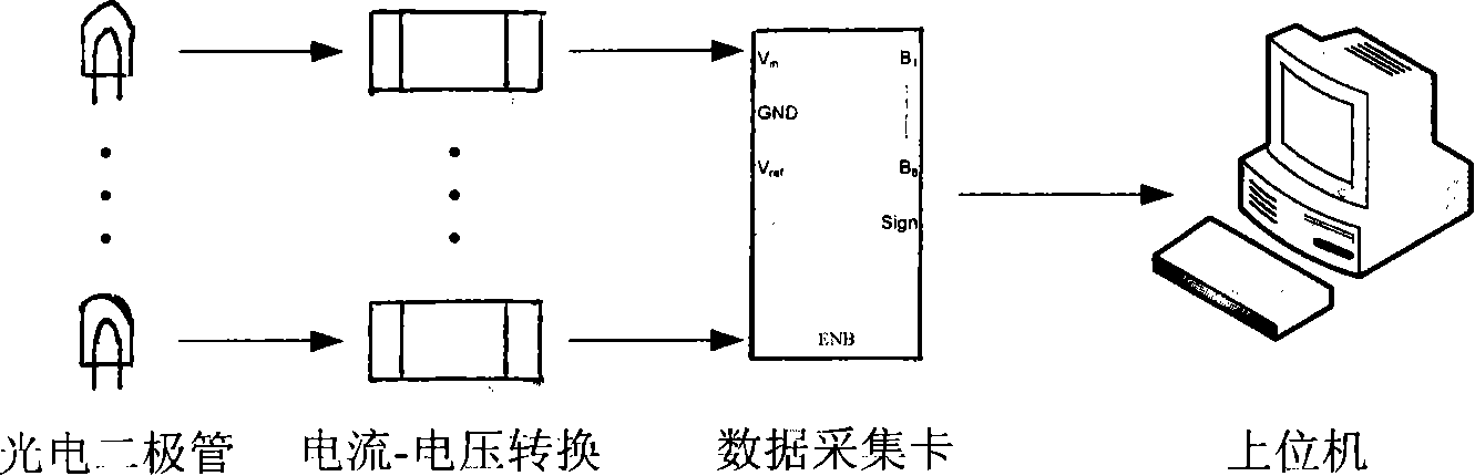
[0022] Please see attached figure 1 . The photodiode converts the illuminance in a certain direction of the sky into a current, converts the voltage through a high-precision operational amplifier, and adjusts the voltage to the required amplitude with a feedback resistor. The signal acquisition system consists of 7 channels. When it is not saturated, the illuminance value of the detection surface is proportional to the brightness value of the direction it is detecting, so the voltage value obtained by the system can reflect the strength of the sky brightness. The response function of the detector to brightness is obtained through the calibration of the radiometer, and the sky brightness value can be obtained from the voltage values ​​detected in all directions when the performance of all detectors is close.

[0023] 1. The selection of the detector mainly considers the requirements of spectral response range and signal linear response range. The spectral range of sunlight i...


PUM


Abstract

The invention discloses a visible and near infrared wave band semispherical sky brightness measuring apparatus used in the daytime. Seven detectors assembled on a semispherical body convert skylight illumination values in various directions into electrical signals, and obtain the spatial distribution of sky brightness via the direct proportional relation between the brightness at the receiving surfaces of the detectors and the illumination and through the calibration of a radiance meter. The method of assembling the seven detectors fixedly on the support of the semispherical body according to vertical angles and azimuths is adopted to obtain the sky brightness values in various directions simultaneously and quickly, thereby not only monitoring the sky brightness in a certain direction in real time, but also monitoring the sky brightness in various directions simultaneously for easy study on the time and spatial distribution of the sky brightness. The apparatus makes up the defects of a traditional sky brightness measuring apparatus concerning measuring wave band, real-time property, portability, etc., thereby meeting the practical scientific research requirements in a better way.

Description

technical field [0001] The invention relates to the field of atmospheric optics, in particular to an instrument for measuring the temporal and spatial distribution of sky brightness in visible and near-infrared bands during the day. Background technique [0002] When using ground-based equipment to detect air targets, the atmosphere cannot be ignored. It redistributes part of the solar radiation energy to form the spatial distribution of scattered light brightness in the atmosphere, that is, the concept of "sky brightness". With the advancement of detection methods, this concept has already been extended from the original specific visible light to infrared and even far infrared bands. On the one hand, in order to obtain radiation information of air or space targets, the influence of the atmosphere must be deducted. When observing an object, the brightness difference between the object and the background plays a decisive role. Therefore, understanding the brightness distri...

Claims


Application Information

Patent Timeline
Patent Type & Authority Applications(China)
IPC IPC(8): G01J1/18G01J1/20
Inventor 李威詹杰饶瑞中
Owner ANHUI INST OF OPTICS & FINE MECHANICS - CHINESE ACAD OF SCI
Why Eureka
Try Eureka