De-coupling capacitance circuit

A capacitive circuit and decoupling technology, which is applied in the direction of circuits, electrical components, electric solid-state devices, etc., can solve problems that do not meet high integration

Inactive Publication Date: 2008-08-27
ETRON TECH INC
View PDF0 Cites 1 Cited by
  • Summary
  • Abstract
  • Description
  • Claims
  • Application Information

AI Technical Summary

Problems solved by technology

However, since the gate oxide capacitance will occupy a large die area, it does not meet the requirements of today's high integration.

Method used


Image

  • De-coupling capacitance circuit
  • De-coupling capacitance circuit
  • De-coupling capacitance circuit

Examples


Embodiment Construction

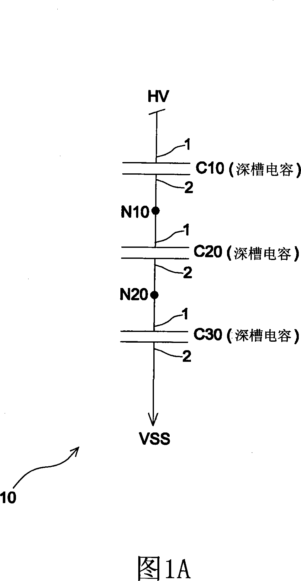
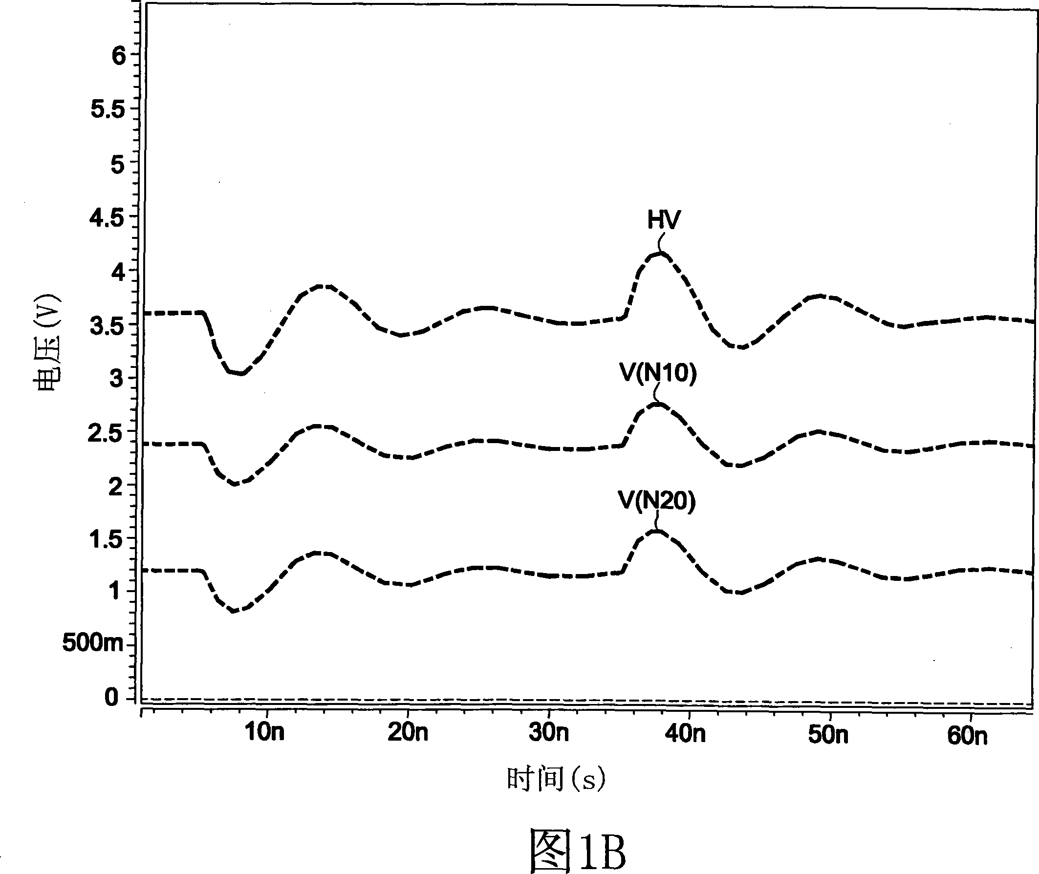
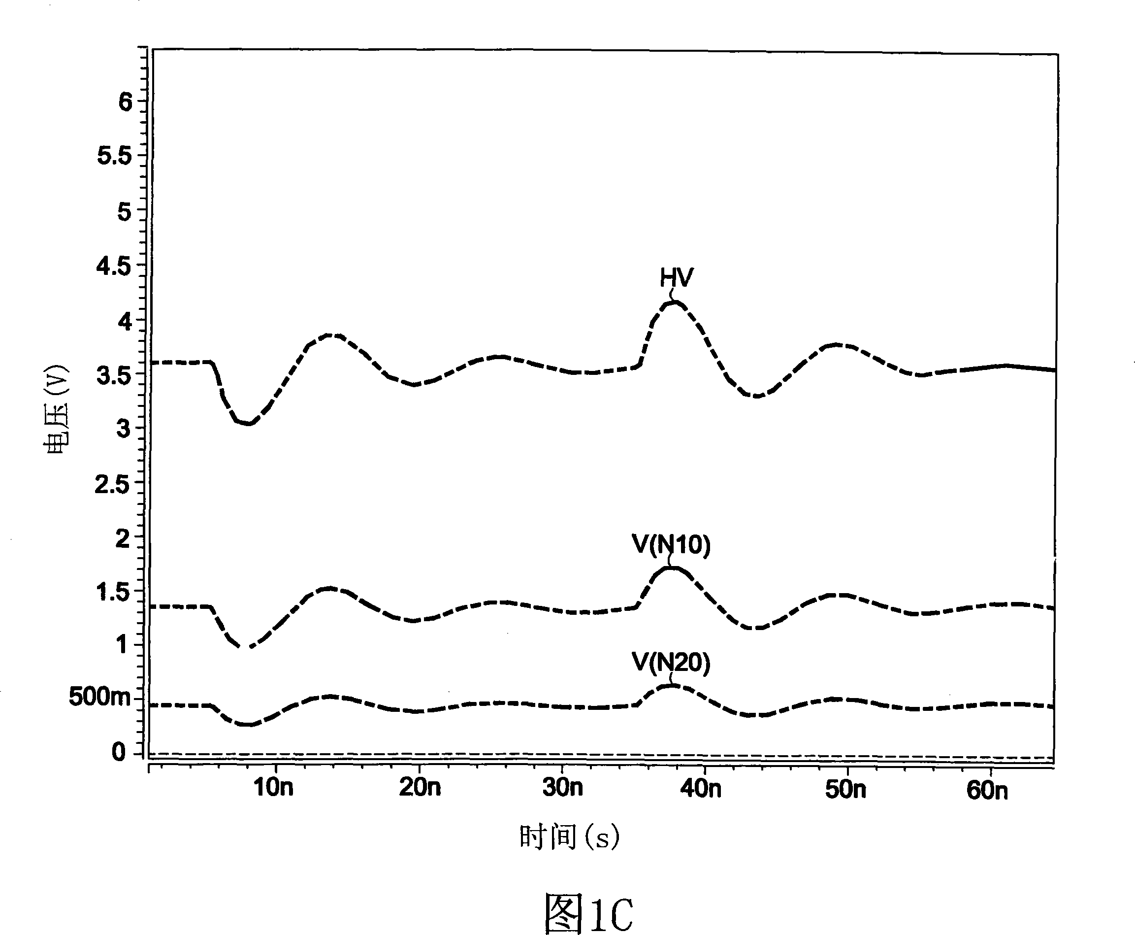
[0018] Currently, deep trench capacitors (DT capacitors) are used in memory cells (cells) of dynamic random access memories (DRAMs), and deep trench capacitors have small areas and large capacities. For example, in a 0.11-micron DRAM manufacturing process, under the same area, the capacitance of deep trench capacitors can be 56 times larger than that of ordinary thick gate oxide capacitors. Therefore, if deep trench capacitors can be used as decoupling capacitors, that is, instead of gate oxide capacitors, the overall die area occupied by gate oxide capacitors can be greatly reduced, and the die size can be improved. particle integration.

[0019] Since the memory cells of the DRAM are applied in the low voltage range, the thickness of most deep trench capacitors is designed to be very thin, so the voltage they can withstand is very low. However, if the deep groove capacitor is used as a decoupling capacitor in a high voltage range such as a power supply, it will have a probl...


PUM


Abstract

A decoupling capacitor circuit comprises a plurality of deep trench capacitors serially connected with one another and a plurality of push-pull circuits. The decoupling capacitor circuit utilizes the push-pull circuits to control the step voltage of each deep trench capacitor, so as to ensure that the step voltage cannot be affected by the defect (leakage current) of the deep trench capacitors or the bias of parasitic elements.

Description

technical field [0001] The invention relates to a decoupling capacitor circuit, in particular to a high voltage decoupling capacitor circuit realized by a deep groove capacitor. Background technique [0002] With the rapid development of science and technology, people have higher and higher requirements for the integration degree and functions of dies. Generally, the power of the die uses a gate oxide capacitor as a power de-coupling capacitor for the power supply. However, since the gate oxide capacitor occupies a relatively large die area, it does not meet the current high-integration requirements. Contents of the invention [0003] In view of the above problems, an object of the present invention is to provide a decoupling capacitor circuit, which can reduce the excessive die area occupied by the gate oxide capacitor. [0004] An embodiment of the present invention provides a decoupling capacitor circuit. The decoupling capacitor circuit includes a plurality of deep ...

Claims


Application Information

Patent Timeline
Patent Type & Authority Applications(China)
IPC IPC(8): H01L27/00H01L27/02
Inventor 许人寿王明弘
Owner ETRON TECH INC
Why Eureka
Try Eureka