Energy-saving vibration-reduction type flux amplification valve

A flow amplification and throttling groove technology, which is applied in fluid pressure actuators, servo motor components, mechanical equipment, etc., can solve the problems of ineffective unloading of steering hydraulic pumps, poor operating comfort of construction machinery, and poor performance of flow amplification valves, etc. problems, to achieve excellent vibration damping effect, strong resistance to oil pollution, and prolong service life

Inactive Publication Date: 2008-09-03
LANZHOU UNIVERSITY OF TECHNOLOGY
View PDF0 Cites 12 Cited by
  • Summary
  • Abstract
  • Description
  • Claims
  • Application Information

AI Technical Summary

Problems solved by technology

At present, the steering hydraulic system has problems such as vibration at start time, crawling vibration, and vibration at stop time, which lead to poor operating comfort of construction machinery; at the same time, the steering hydraulic pump cannot be effectively unloaded, resulting in high energy consumption of the system, temperature rise, The main reason for the above problems is the poor performance of the flow amplification valve.
Foreign companies such as Kawasaki Heavy Industries, DANFOSS, Carter and other companies have developed some flow amplification valves with better performance, but their structures are more complicated and expensive.

Method used


Image

  • Energy-saving vibration-reduction type flux amplification valve
  • Energy-saving vibration-reduction type flux amplification valve
  • Energy-saving vibration-reduction type flux amplification valve

Examples


Embodiment Construction

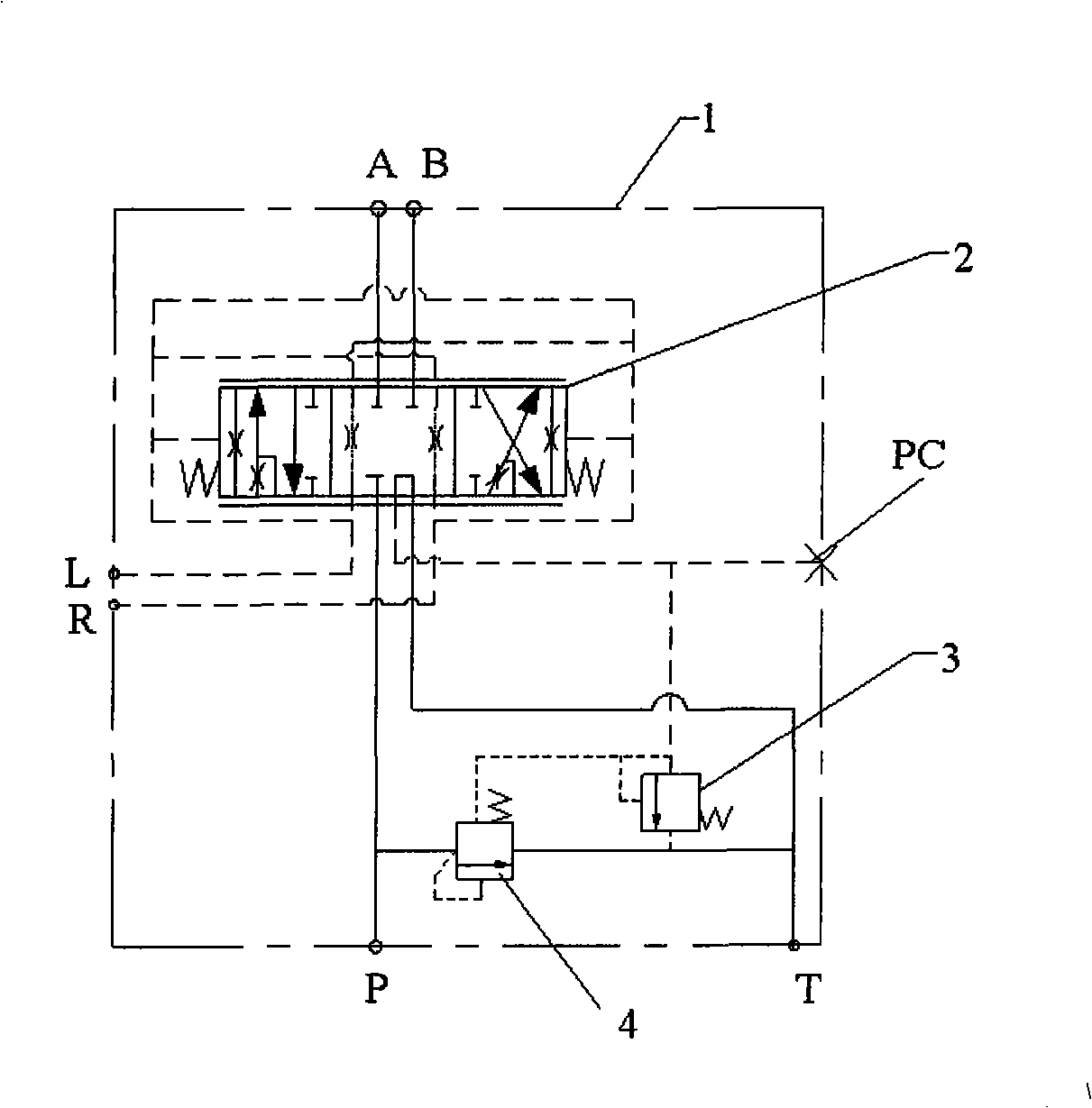
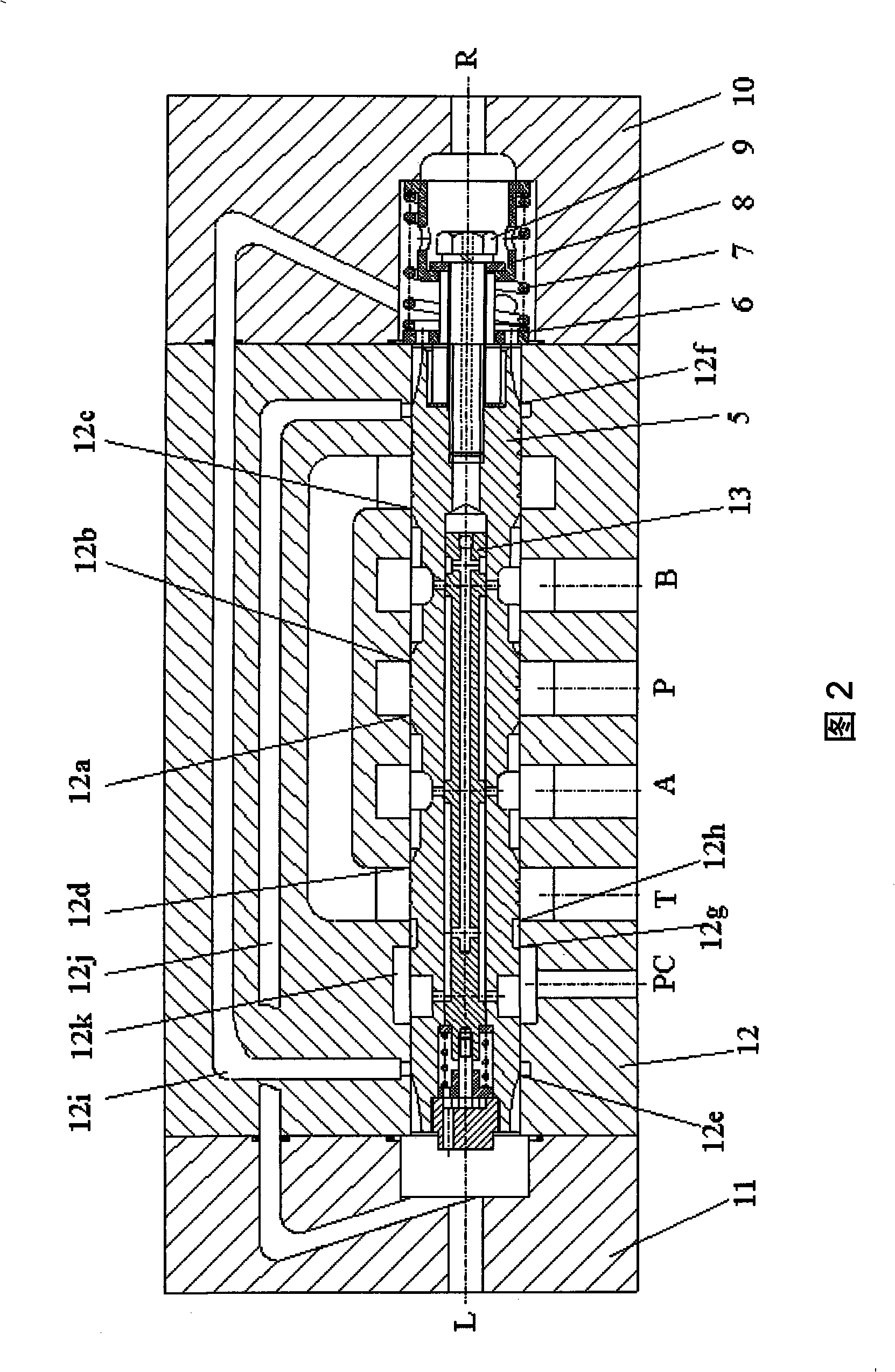
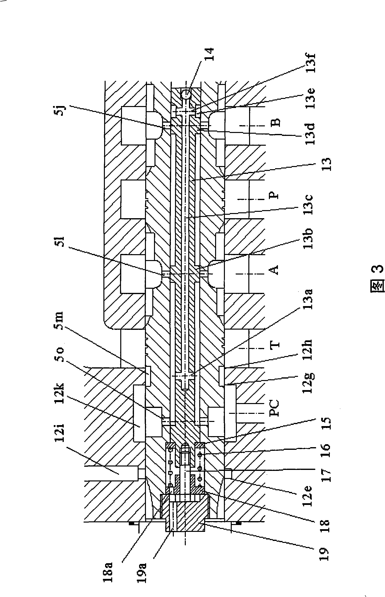
[0008] Such as Figure 1 ~ Figure 4 As shown, the energy-saving and vibration-reducing flow amplifying valve 1 includes a hydraulic proportional directional valve 2, a safety valve 3, and a differential overflow valve 4, and the hydraulic proportional directional valve 2 includes a main valve core 5, a small valve core 13, a spring 7, small valve spring 16, valve body 12, right valve cover 10, left valve cover 11. The main valve core 5 is kept in the middle position of the valve body 12 by the retaining ring 6, the spring 7, the spring seat 8, the hollow screw 9, and the right valve cover 10. The small valve core 13 in the main valve core 5 is formed by the small valve retaining ring 15, Small valve spring 16, screw 17, small valve spring seat 18, screw plug 19 are kept in the middle position in the main valve core 5, and there are four throttling groove groups in the middle of the main valve core 5, and the four throttle groove groups are about the main valve core 5. The SS ...


PUM


Abstract

The present invention provides an energy-saving damping type amplificative valve. Four throttling groove groups are symmetrical with midline of the main valve core 5, the throttling groove groups on two sides of midline comprise a first oil trough 5a, a second oil trough 5b, a third oil trough 5c and a fourth oil trough 5d in pair respectively, the other two throttling groove groups comprise a first oilreturning groove 5e, a second oilreturning groove 5f, a third oilreturning groove 5g and a fourth oilreturning groove 5h in pair respectively, four throttling groove groups form four main valve port respectively with the first oil intake throttling edge 12a, the second oil intake throttling edge 12b, the first oilreturning throttling edge 12c, the second oilreturning throttling edge 12d, the pilot valve throttling grooves 5i on two ends of the main valve core 5 form two pilot valve port with the first pilot valve throttling edge 12e and the second pilot valve throttling edge 12f on two ends of valve body 12 respectively, the first ring groove 5m and the second ring groove 5n are provided on the left of the main valve core 5, an oil guide ring groove 12k are arranged on the corresponding position of the valve body 12, the first unloading edge 12g and the second unloading edge 12h are provided on the valve body 12 corresponding the position of the first ring groove 5m, seven external connection oil ports are provided on the valve body 12.

Description

technical field [0001] The invention relates to a hydraulic proportional reversing valve, in particular to a flow amplifying valve. Background technique [0002] The hydraulic flow amplification valve is widely used in the steering hydraulic system of medium and large construction machinery. Its function is to amplify the flow and hydraulic power of the pilot control flow output by the steering gear according to a certain amplification factor, and control the movement of the hydraulic actuator. At present, the steering hydraulic system has problems such as vibration at start time, crawling vibration, and vibration at stop time, which lead to poor operating comfort of construction machinery; at the same time, the steering hydraulic pump cannot be effectively unloaded, resulting in high energy consumption of the system, temperature rise, The main reason for the above problems is the poor performance of the flow amplification valve. Foreign companies such as Kawasaki Heavy Ind...

Claims


Application Information

Patent Timeline
Patent Type & Authority Applications(China)
IPC IPC(8): F15B13/02
Inventor 冀宏谭正生王峥嵘张玮魏列江
Owner LANZHOU UNIVERSITY OF TECHNOLOGY
Why Eureka
Try Eureka