Packaging structure of plane waveguide light shunt and preparation method thereof

A technology of planar waveguide and optical splitter, which is applied in the field of optical fiber, can solve the problems of difficult use process, packaging and transportation, cumbersome manufacturing process, and large overall volume, and achieve the effects of being suitable for mass production, reducing manufacturing processes, and protecting optical fibers

Inactive Publication Date: 2008-09-03
BROADEX TECH
View PDF0 Cites 16 Cited by
  • Summary
  • Abstract
  • Description
  • Claims
  • Application Information

AI Technical Summary

Problems solved by technology

The traditional manufacturing method is as follows: first seal the planar waveguide optical branch core into the corresponding outer envelope, then perform full splitting of the pigtail beyond a certain length, and then penetrate the loose tube and fix the optical fiber on the splitter, Finally, the connector is made, so the production process is more cumbersome, and there is a section of unprotected ribbon fiber remaining outside the outer casing, without the protection of the fiber sleeve, it is easy to cause damage to the fiber, and at the same time, the overall volume is caused by the addition of an additional splitter structure. Larger, more difficult to use, package and transport

Method used


Image

  • Packaging structure of plane waveguide light shunt and preparation method thereof
  • Packaging structure of plane waveguide light shunt and preparation method thereof
  • Packaging structure of plane waveguide light shunt and preparation method thereof

Examples


Embodiment

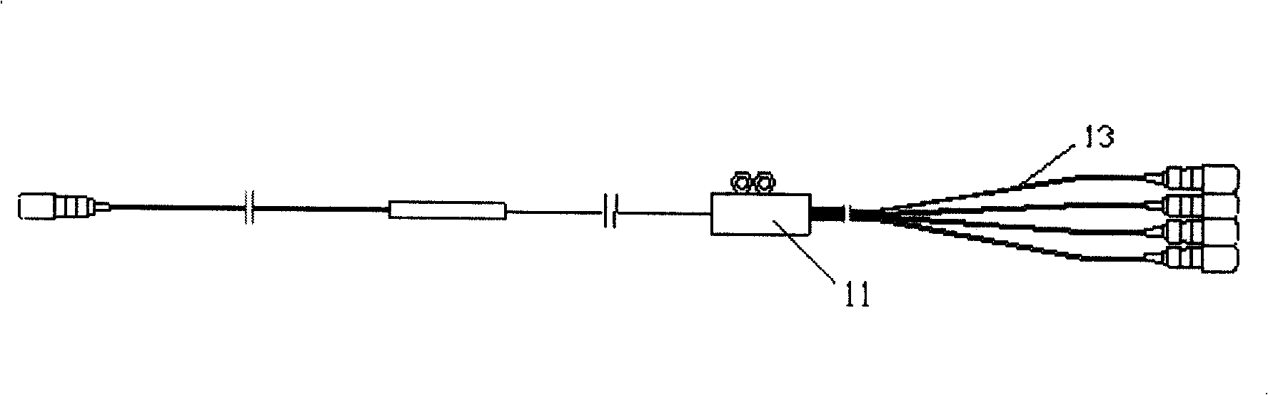
[0030] Embodiment: Below we describe the method of the present invention according to the packaging method of the 900 micron fiber sleeve output of the 1x8 planar waveguide optical splitter, but it should be understood that the method of the present invention is also applicable to other MxN planar waveguide optical splitters.

[0031] The present invention provides a packaging structure and packaging method of a planar waveguide optical splitter as follows:

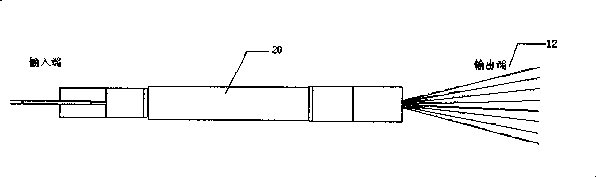
[0032] Step 1: If Figure 3A , splitting the output end (12) of the planar waveguide splitter core (20) into a single optical fiber;

[0033] Step 2: If Figure 3A , fixing the planar waveguide splitter core (20) on the working frame;

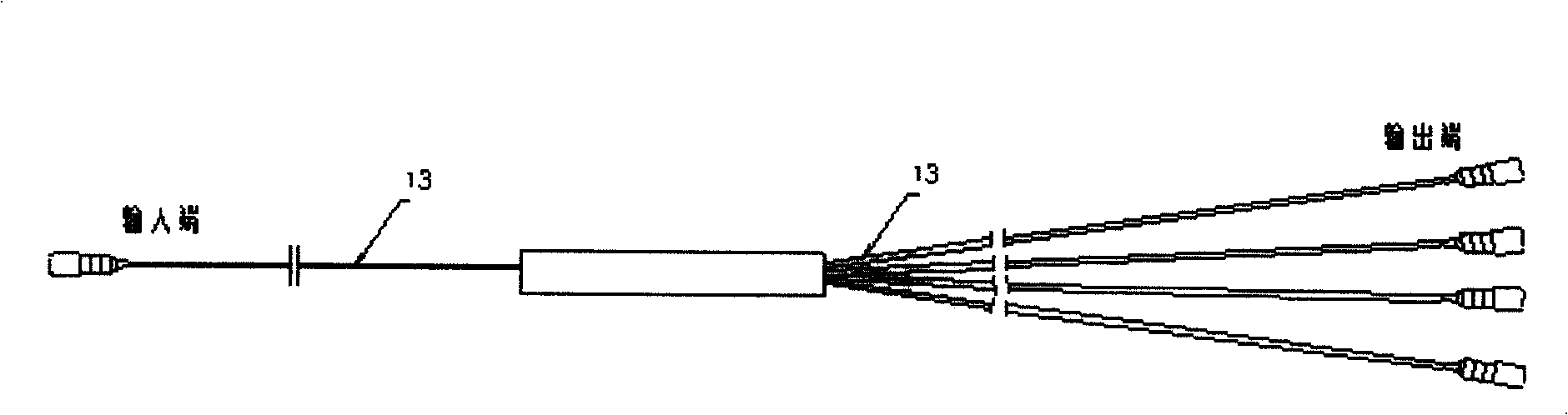
[0034] Step 3: If Figure 3B , the 900 micron loose tube (13) and the input end rubber cap (14) are fixed together to produce the input end rubber cap assembly (15);

[0035] Step 4: If Figure 3C , 8 900 micron loose tubes (13) at the output end and the output end rubber cap (16) are...


PUM


Abstract

The invention relates to a packaging structure of plane waveguide optical branching device and preparation method. A plane waveguide optical branching device core (20) is fixed in the lower casing (18) of the outer casing. A rubber cap module (15) of input end and rubber cap module (17) of output end respectively pass through from the two ends of the branching device core (20) and are fixed at the port of the lower casing (18) to directly output the optical fiber loose sleeve (13). The optical fiber of input end and optical fiber of the output end are all protected by the loose sleeve (13). The top casing (19) of the outer casing is fixed on the lower casing (18) of the outer casing. The new optical fiber loose sleeve is directly output, therefore the method can effectively increase the production efficiency of the optical branching device and reduce the production step of the traditional branching device, and the optical fiber of input end and optical fiber of the output end obtain the protection of the whole loose sleeve, with compact whole structure, safety, reduced cost, suitable for production in enormous quantities.

Description

technical field [0001] The invention belongs to the field of optical fiber technology, in particular to a compact packaging structure of a planar waveguide optical splitter and a preparation method thereof. Background technique [0002] With the widespread use of planar optical waveguide devices, planar waveguide optical splitters have broad application prospects as the core device of fiber-to-the-home networks. In order to facilitate customer use and reduce costs, it is necessary to optimize product structure, reduce manufacturing processes, and improve manufacturing efficiency. . [0003] The planar waveguide optical splitter is mainly composed of an input-end optical fiber array, a planar waveguide chip and an output-end optical fiber array to form a planar waveguide optical splitter. As the core device of the fiber-to-the-home network, the planar waveguide optical splitter needs to be connected to the system through an adapter after assembling the connectors at both end...

Claims


Application Information

Patent Timeline
Patent Type & Authority Applications(China)
IPC IPC(8): G02B6/28
Inventor 丁勇刘琳闫超
Owner BROADEX TECH
Why Eureka
Try Eureka