
Pulsed plasma thruster with ceramic air spout electrode

A pulsed plasma and ceramic nozzle technology, applied in the field of thrusters, can solve the problems of low propellant utilization, improve thruster performance, and low propellant efficiency, and achieve the goals of improving electrothermal acceleration efficiency, saving propellant, and improving efficiency Effect

Inactive Publication Date: 2008-09-10
SHANGHAI JIAO TONG UNIV
View PDF0 Cites 23 Cited by
  • Summary
  • Abstract
  • Description
  • Claims
  • Application Information

AI Technical Summary

Problems solved by technology

[0003] Found through literature search to relevant technology, " Investigation of propellant inefficiencies in a pulsed plasma thruster " (pulse plasma thruster " published by Gregory G.Spanjers et al. Propellant Low Efficiency Research), the paper proposes that the low efficiency of the pulsed plasma thruster is due to the low acceleration efficiency caused by the low utilization rate of the propellant, and improving the efficiency of the thruster should increase the acceleration efficiency of the propellant
Its shortcoming is that it does not give a specific method to improve the performance of the thruster

Method used


Image

  • Pulsed plasma thruster with ceramic air spout electrode
  • Pulsed plasma thruster with ceramic air spout electrode
  • Pulsed plasma thruster with ceramic air spout electrode

Examples


Embodiment Construction

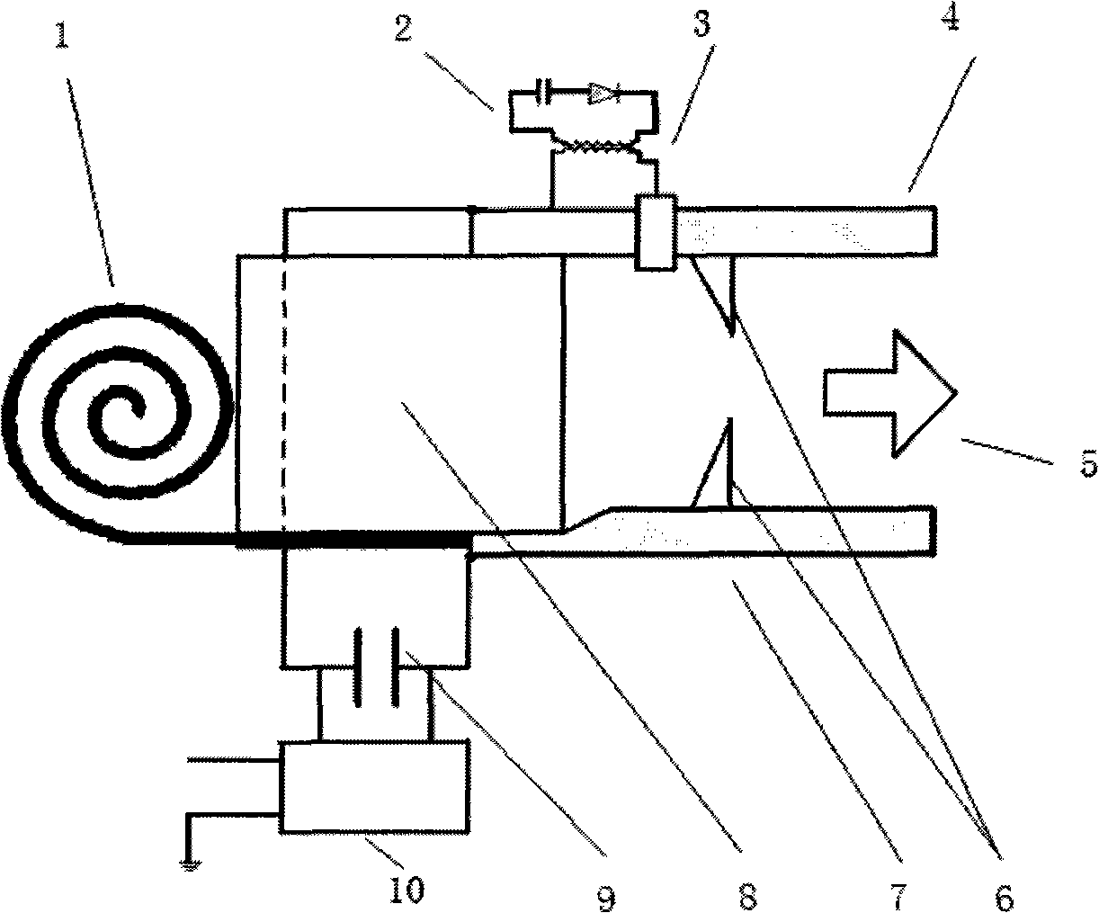
[0012] The embodiments of the present invention are described in detail below in conjunction with the accompanying drawings: this embodiment is implemented on the premise of the technical solution of the present invention, and detailed implementation methods and specific operating procedures are provided, but the protection scope of the present invention is not limited to the following the described embodiment.

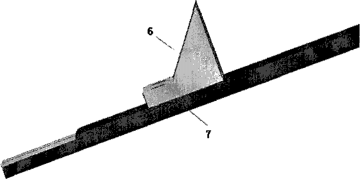
[0013] Such as figure 1 As shown, this embodiment includes: feed spring 1, ignition circuit 2, spark plug 3, cathode 4, anode 7, ceramic nozzle 6, propellant 8, high voltage capacitor 9, charging power source 10 and thruster housing. The tail of the feed spring 1 is expanded and pressed under the propellant 8 to generate a feed force to the propellant 8; the ignition circuit 2 provides the spark plug 3 with electric energy for ignition and discharge; the spark plug 3 is fixed on the cathode 4 through an external thread; the propellant 8 The horizontal direction is fi...


PUM


Abstract

The invention relates to a pulse plasma thruster provided with a ceramic nozzle electrode in the mechanical technical field, wherein, the tail of a feeding spring is unfolded and pressed under propellants and generates a feeding force for the propellants; a firing circuit supplies electrical energy to a spark plug for ignition and discharge; the spark plug is fixed on a cathode; the propellants are horizontally fixed by the feeding spring and a lug boss of an anode and vertically fixed by the cathode and the anode; a high-voltage capacitor is connected wit the cathode and the anode; and a power source is connected to a binding post of the high-voltage capacitor through a wire. The invention designs an electrode structure provided with a microcrystal mica ceramic nozzle to replace the prior parallel electrode through analysis of the operating process of the thruster. The invention is characterized by improvement of the pressure of a discharging area and the electric heating acceleration, thereby the thrust and the efficiency of the pulse plasma thruster are greatly improved.

Description

technical field [0001] The invention relates to a thruster in the technical field of power machinery, in particular to a pulse plasma thruster with a ceramic nozzle electrode. Background technique [0002] Traditional chemical propulsion has low specific impulse, large mass, and complex structure, which greatly limits its application in microsatellites. The pulse plasma thruster, which emerged in the 1960s, is a small-thrust electromagnetic electric thruster, which has the advantages of high specific impulse and small mass, and can be applied to attitude control, orbit transfer and lifting, and orbit correction of micro-satellites , drag compensation, position maintenance, repositioning, and off-orbit handling tasks, compared with chemical propulsion, it can greatly save propellant and reduce launch costs. In 1974, a pulsed plasma thruster of the United States was deployed on a geosynchronous meteorological satellite (SMS); in 2000, NASA used a pulsed plasma thruster on the...

Claims


Application Information

Patent Timeline
IPC IPC(8): F03H1/00
Inventor 康小明侯大立赵万生
Owner SHANGHAI JIAO TONG UNIV
Features
  • Generate Ideas
  • Intellectual Property
  • Life Sciences
  • Materials
  • Tech Scout
  • Unparalleled Data Quality
  • Higher Quality Content
  • 60% Fewer Hallucinations
Learn More