Separation driving circuit and control method with discharging channel

A technology for isolating drive circuits and discharge paths, applied in electrical components, output power conversion devices, etc., can solve the problems of inability to change voltage, large resistance value of resistor R2, and low level of driving waveform, and achieve the effect of avoiding false conduction.

Inactive Publication Date: 2008-09-17
SHENZHEN AEROSPACE NEW POWER TECH
View PDF0 Cites 27 Cited by
  • Summary
  • Abstract
  • Description
  • Claims
  • Application Information

AI Technical Summary

Problems solved by technology

[0007] In order to solve the problem in the prior art that when the duty cycle of the pulse square wave waveform sent by the control or drive chip decreases rapidly, the primary side DC blocking capacitor and the primary side excitation inductance of the driving transformer will resonate, and the bootstrap of the secondary side of the driving transformer Capacitor C2 can only be discharged through resistor R1 and resistor R2, and usually the resistance value of resistor R2 is relatively large, so that the voltage across it cannot change according to the rapid change of duty cycle, and the final driving waveform has a high low level and cannot be turned off. To solve technical problems such as disconnecting the driven power switch tube, the invention provides an isolated drive circuit with a discharge path

Method used


Image

  • Separation driving circuit and control method with discharging channel
  • Separation driving circuit and control method with discharging channel
  • Separation driving circuit and control method with discharging channel

Examples


Embodiment Construction

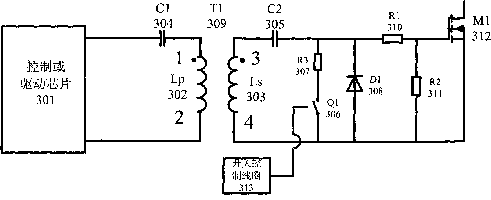
[0029] The technology of the present invention is based on the traditional isolated drive circuit, and a controllable discharge circuit is connected in parallel at both ends of the bootstrap diode 308 on the secondary side. When the duty cycle of the primary side changes rapidly from large to small, the bootstrap capacitor 305 on the secondary side can ensure rapid discharge, so that the low level of the final output driving signal is reduced to zero, preventing false conduction of the subsequent power switch tube.

[0030] The present invention is described below in conjunction with accompanying drawing:

[0031] see image 3 Schematic diagram of the isolated drive circuit with discharge path of the present invention, such as image 3 As shown, the primary side input signal interface, the driving pulse from the control circuit enters the circuit of the present invention; the primary side DC blocking capacitor C1304 is connected to the driving pulse entrance and the primary s...


PUM


Abstract

The present invention provides an isolation driving circuit having a discharge path and its control method. The isolation driving circuit includes a control or driving unit, a driving transformer unit and a secondary line bootstrap circuit, the secondary line bootstrap circuit includes a bootstrap capacitor; the isolation driving circuit also includes a discharge circuit discharging for the bootstrap capacitor, the discharge circuit is parallel with the bootstrap diode, the discharge circuit further includes a switch, processing by passing the auxiliary winding. The control method of the isolation driving circuit includes: when the driving pulse of the isolation driving circuit is a high level, the bootstrap capacitor discharge circuit is turned off, the isolation driving circuit outputs the high level; when the driving pulse of the isolation driving circuit is a lower level, the bootstrap capacitor discharge circuit is turned on, the lower level of the isolation driving circuit output is zero. The invention ensures the normal working of the driving circuit when the duty cycle is large change. The auxiliary winding coil and the auxiliary switch can provide quick discharge circuit to the secondary line bootstrap capacitor, avoiding the miss guide of the power switch tube which is switched.

Description

technical field [0001] The invention belongs to the field of switching power supplies, and relates to a drive circuit applied to a power switch tube of a switching power supply, in particular to an isolated drive circuit with a discharge path for a high-side power switch tube and a control method thereof. Background technique [0002] For a high-frequency switching power supply, the driving pulse from the control circuit needs to be isolated from the power switching tube due to the topology itself or for circuit safety considerations. [0003] The power switch tube isolation drive circuit in the prior art is shown in the accompanying drawings figure 1 As shown, it includes: control or drive chip, primary side DC blocking capacitor C1, isolation drive transformer T1, secondary side bootstrap capacitor C2, bootstrap diode D1, resistors R1 and R2. [0004] The pulse square wave signal sent by the control or drive chip is transmitted to the secondary side through the primary si...

Claims


Application Information

Patent Timeline
Patent Type & Authority Applications(China)
IPC IPC(8): H02M1/08
Inventor 张东来王毅佟强姚雨迎王骞
Owner SHENZHEN AEROSPACE NEW POWER TECH
Why Eureka
Try Eureka