Sound wave detection control method and device

A control method and sonic detection technology, which are used in the analysis of solids, infrastructure tests, buildings, etc. using sonic/ultrasonic/infrasonic waves.

Inactive Publication Date: 2008-09-24
WUHAN RSM INTELLIGENC GEOTECHN
View PDF1 Cites 20 Cited by
  • Summary
  • Abstract
  • Description
  • Claims
  • Application Information

AI Technical Summary

Problems solved by technology

[0015] (2) The number of lifting detection processes; usually the length of the connecting cable between the acoustic wave sensor and the acoustic wave instrument is tens of meters or even hundreds of meters, and each lifting detection process needs to move and place the sound wave between different acoustic measuring tubes. sensor, inconvenient
This channel switching method has relatively large defects: 1) one transmission only corresponds to one reception, and the work efficiency is low; 2) the acoustic wave sensor is switched by a single-pole 3-throw relay switch, which relies on the mechanical movement of the contacts After the switching is completed, the relay switch is easy to be damaged; 3) When the acoustic wave sensor is switched from the transmitting state to the receiving state, the acoustic wave sensor

Method used


Image

  • Sound wave detection control method and device
  • Sound wave detection control method and device
  • Sound wave detection control method and device

Examples


Embodiment 1

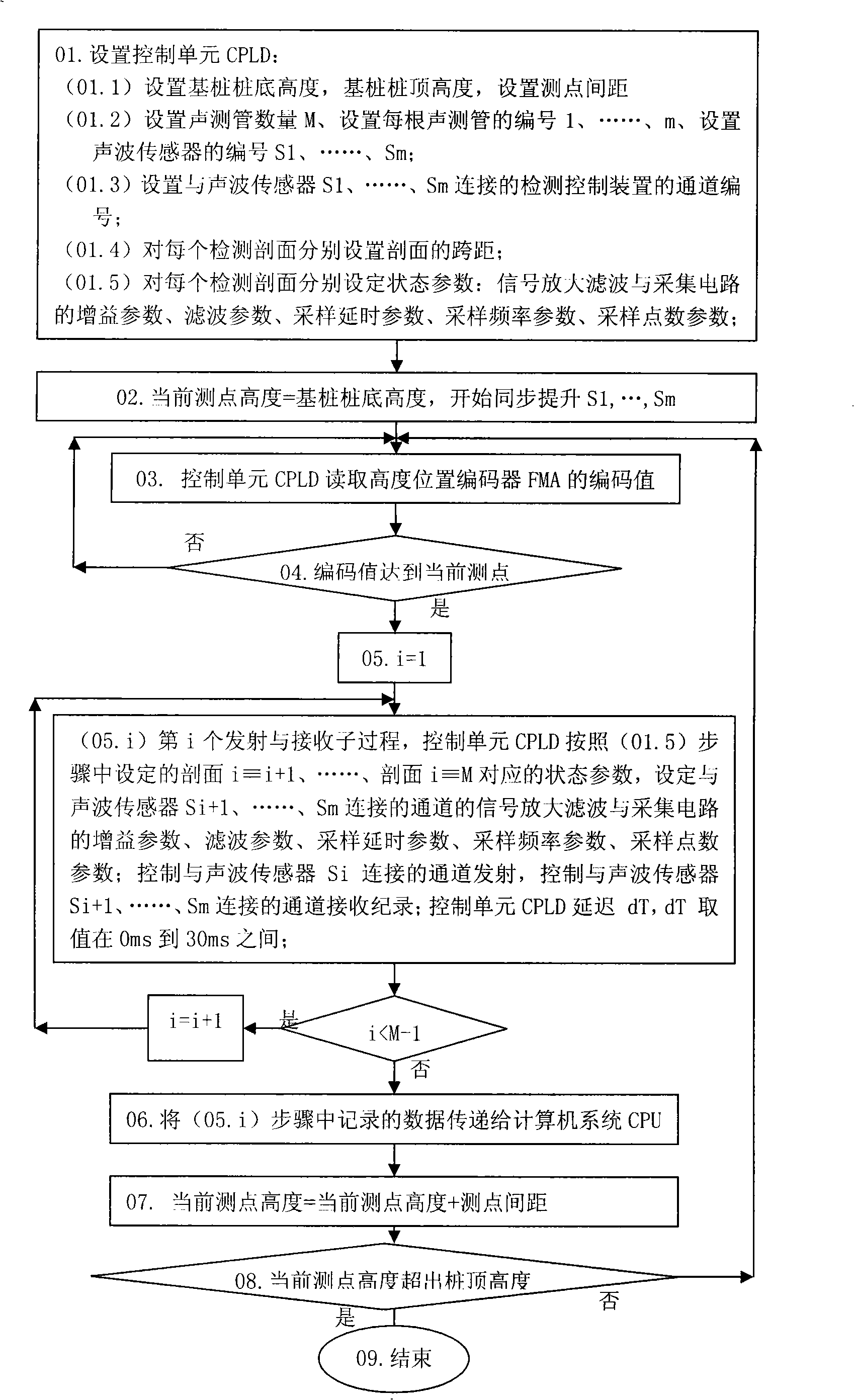
[0100] Embodiment 1: a 4-channel sound wave detection control method, the steps of which are as follows:

[0101] For foundation piles with 4 acoustic tubes buried,

[0102] The jth (1≤j≤4) channel Chj in the 4 channels of the detection control device is composed of the transmitting terminal Aj of the acoustic wave transmitter A, the transceiver half-duplex circuit Tj, and the signal amplification filter and acquisition circuit Ij;

[0103] A dual-purpose acoustic wave sensor is placed in the acoustic tubes numbered 1, 2, 3, and 4, respectively, and the dual-purpose acoustic wave sensor placed in the acoustic tube i (1≤i≤4) is marked as Si;

[0104] The height positions of the four dual-purpose acoustic wave sensors S1, S2, S3, and S4 are the same, and the cables of the acoustic wave sensors S1, S2, S3, and S4 can drive the height position encoder FMA to roll during the lifting process;

[0105] The 4 acoustic wave sensors S1, S2, S3 and S4 for transceivers are respectively c...

Embodiment 2

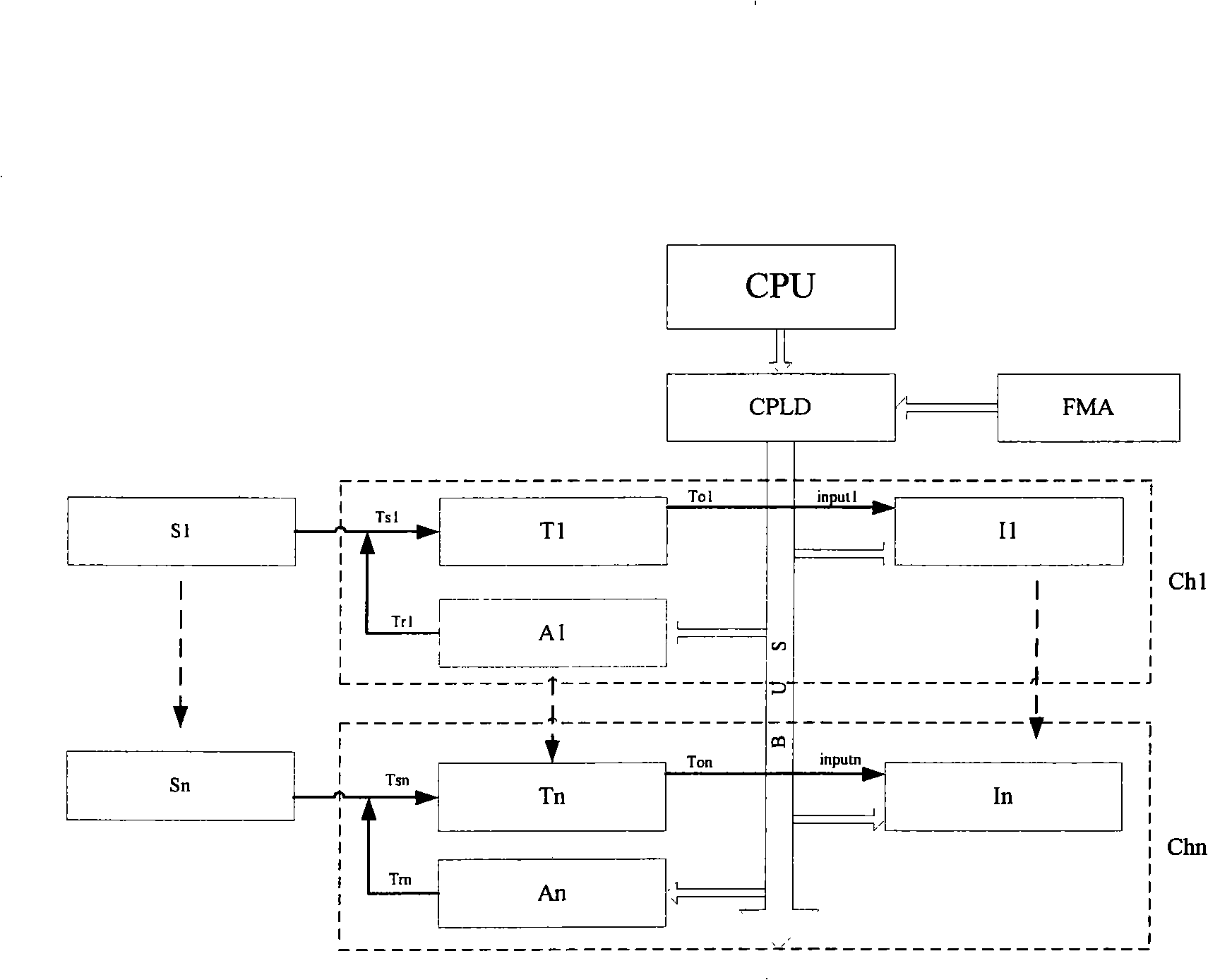
[0126] Embodiment 2: a kind of device that realizes 4-channel sound wave detection control method, it has following components to form:

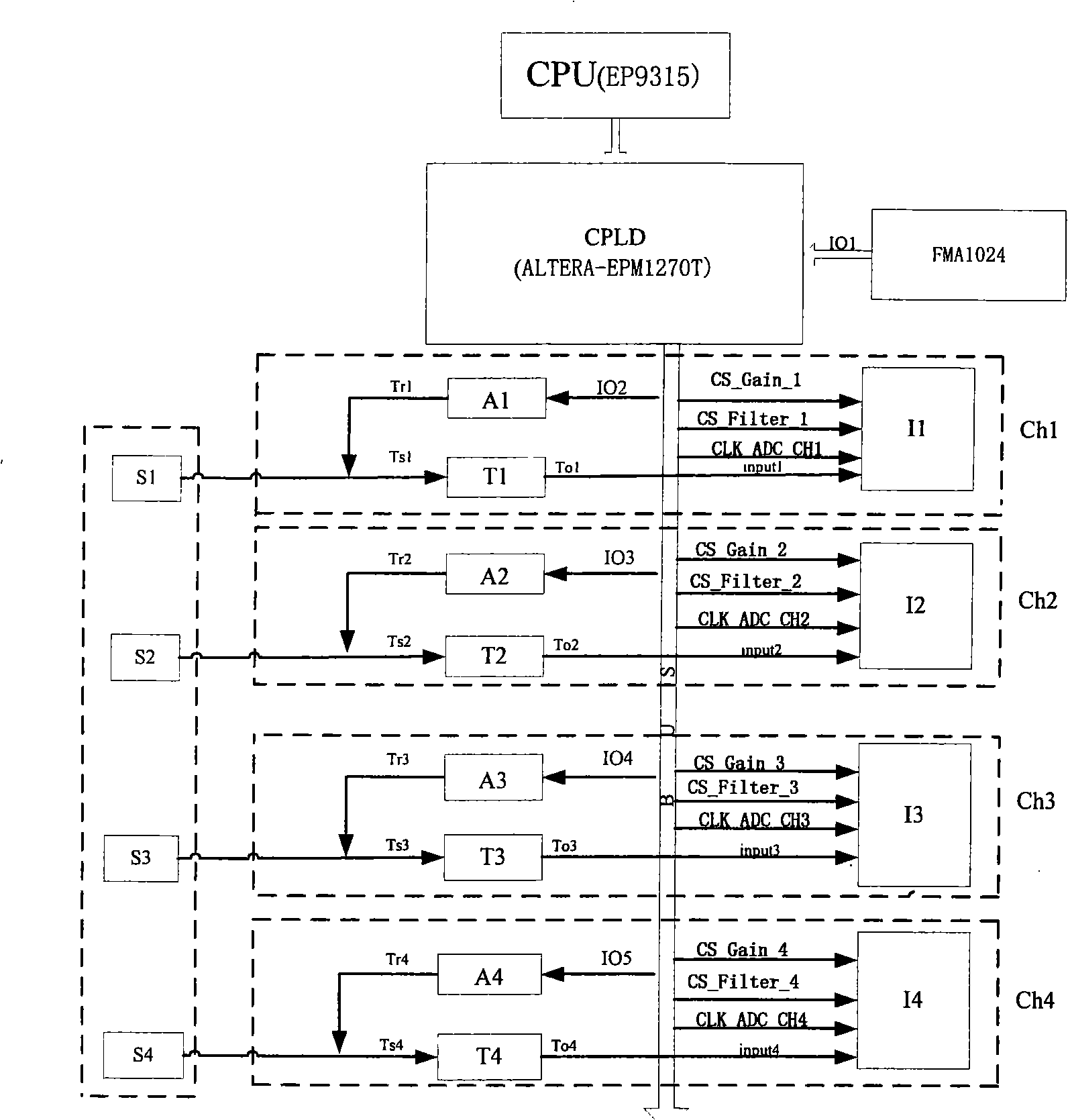
[0127] according to figure 2 , image 3 It can be seen that the sound wave detection control device consists of 4 YGD-45KHz transceiver dual-purpose acoustic wave sensors S1, S2, S3, S4, 4 transceiver dual-purpose channels Ch1, Ch2, Ch3, Ch4 (one wonhere1.4 type has 4 transmitting terminals Acoustic wave transmitter A of A1, A2, A3, A4, 4 transceiver half-duplex circuits T1, T2, T3, T4, 4 signal amplification filtering and acquisition circuits I1, I2, I3, I4), 1 computer system EP9315CPU , a control unit ALTERA-EPM1270T CPLD, a FMA 1024 photoelectric encoder.

[0128] according to figure 2 , image 3 It can be seen that the i-th transceiver channel Chi is composed of the i-th transceiver half-duplex circuit Ti, the i-th signal amplification filter and acquisition circuit Ii, the i-th transmitting terminal Ai of the wonhere1.4 acoustic ...


PUM


Abstract

The invention discloses a sound wave detecting control method and device. The steps include: A, setting a control unit; B, setting a height of the current detecting point and beginning to synchronously lift wave sound sensors; C, reading the height positions of the wave sound sensors S1, Sm; D returning to the step C if the height position does not reach the height of the current detecting point; E, carrying out sub-processes of emitting and receiving with a number of M-1; F, transferring the data recorded into step E to a computer system; G, calculating a new height of the current detecting point; H, returning to step C if the height of the current detecting point is not higher than the height of the top of a foundation pile; finishing when the height of the current detecting point is higher than the height of the top of the foundation pile. The device consists of N receiving-emitting convertible wave sound sensors S1, Sn; N receiving-emitting convertible channels Ch1, Chn, a computer system CPU, a control unit CPLD and a height position coder FMA. The device can finish the detecting work of all the section planes formed by M sound detecting pipes in the pile foundation during a lifting detecting process and have a high detecting efficiency.

Description

technical field [0001] The invention belongs to the technical field of applying the acoustic wave transmission method to detect the integrity of foundation piles in the field of geotechnical engineering detection, in particular to an acoustic wave detection control method, and also to an acoustic wave detection control device. Background technique [0002] Integrity of foundation piles detected by acoustic transmission [0003] The integrity of cast-in-place piles should be detected by the acoustic wave transmission method in geotechnical engineering. Before pouring concrete, M (2≤M) acoustic measuring tubes parallel to each other should be pre-placed on the reinforcement cage of the foundation pile, and the length of the acoustic measuring tube should be Consistent with the length of the pile (the length of the reinforcement cage), after the concrete pouring of the pile body is completed, the acoustic measuring tubes are embedded in the pile body, and the i-th (1≤i≤M) acous...

Claims


Application Information

Patent Timeline
IPC IPC(8): E02D33/00G01N29/04
Inventor 张杰刘玉胡纯军邹宇李长林
Owner WUHAN RSM INTELLIGENC GEOTECHN
Why Eureka
Try Eureka