LED focus lamp

A technology for LED spotlights and spotlighting devices, applied in the directions of light sources, headlights, point light sources, etc., can solve the problem of the formation of spotlights that are not stated, and achieve the effect of reducing color unevenness

Inactive Publication Date: 2008-09-24
NEC LIGHTING
View PDF4 Cites 28 Cited by
  • Summary
  • Abstract
  • Description
  • Claims
  • Application Information

AI Technical Summary

Problems solved by technology

[0009] The invention in Japanese Patent Laid-Open No. 2004-212469 discloses using a plurality of LED lamps and inputting beams into a rod integrator that provides uniform outgoing light with high light intensity, but does not state the formation of a spotlight

Method used


Image

  • LED focus lamp
  • LED focus lamp
  • LED focus lamp

Examples


Embodiment Construction

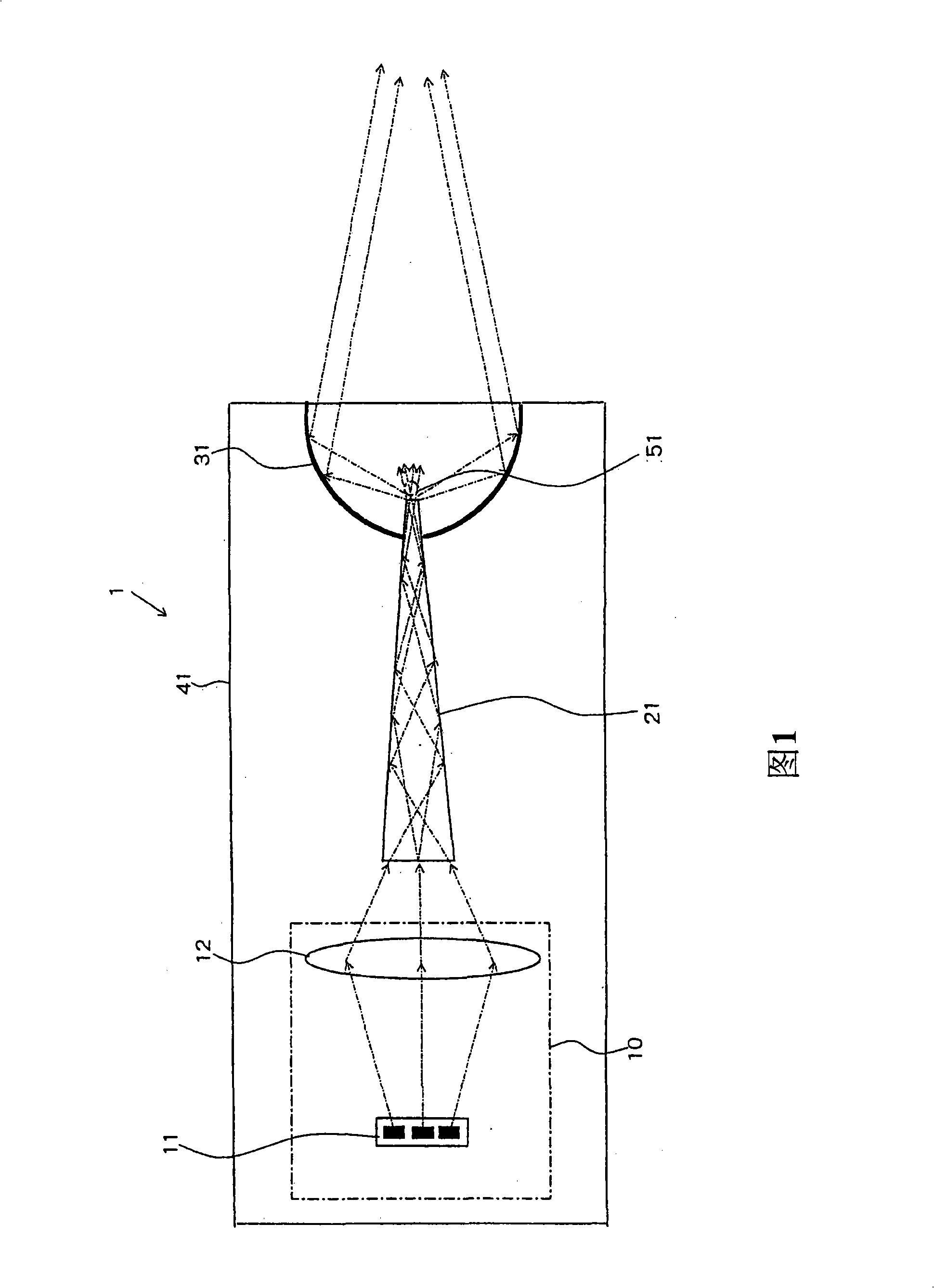
[0027] Next, a first exemplary embodiment of the present invention will be described with reference to the drawings. Fig. 1 is a schematic side view of an LED spotlight according to a first exemplary embodiment of the present invention.

[0028] The LED spotlight 1 of the first exemplary embodiment of the present invention includes an RGB-LED light source 11 , a light source unit 10 , a tapered rod lens 21 , a reflector 31 , and a housing 41 .

[0029] The light source unit 10 has a first condenser lens 12 . The first condensing lens 12 is a first condensing device for converging the color-mixed light beam projected from the RGB-LED light source 11 onto the incident surface of the rod lens 21 . The tapered rod lens 21 is a tapered lens whose cross section converges toward the exit surface. The reflection mirror 31 condenses the light emitted from the emission surface of the tapered rod lens 21 to form a point light source 51 . Here, the first light collecting means is descr...


PUM


Abstract

LED focus lamp includes a RGB-LED light source composed of red, green and blue LEDs and a focus lens that assembles mixed beams projected from the RGB-LED light source to an incident end face; a cone-shaped stick lens, a section of which is convergent from the incident end face to an exit end face; a reflector that assembles the exit light taking the incident face of the cone-shaped stick lens as a point light source to an axis of the cone-shaped stick lens. The beam incident to the cone-shaped stick lens is reflected for a plurality of times inside when the beam matches, which reduces unevenness of the brightness in the exit end face of the stick lens and accelerates color mix, enabling the beam to be�÷•õ from a white light point of same colors from any direction and the beam is a focused light assembled on the axis of the cone-shaped stick lens by the reflector.

Description

[0001] This application is based on and claims priority from Japanese Patent Application No. 2007-070521 filed on March 19, 2007, the disclosure of which is hereby incorporated by reference in its entirety. technical field [0002] The invention relates to an LED spotlight using LED as a light source, in particular to an LED spotlight comprising a rod lens. Background technique [0003] LED (Light Emitting Diode) has features such as low power consumption, long life, less heat generation, fast response and space saving. As a result, LEDs are widely used in lighting applications, where they are used as light sources, and in applications ranging from traffic lights to automotive headlights, where they have found utility. [0004] On the one hand, the light from the LED has the characteristic that the light intensity changes based on the light exit angle. Therefore, it is difficult to control light distribution by using a reflector compared to the case of using a light bulb. ...

Claims


Application Information

Patent Timeline
Patent Type & Authority Applications(China)
IPC IPC(8): F21V13/04F21V5/04F21V7/00F21Y101/02F21K99/00
CPCF21S48/1127F21S48/1159F21V2008/00F21V7/0091F21W2101/10F21Y2101/02F21S48/1241F21Y2113/00F21S48/1154F21S41/12F21S41/143F21S41/148F21S41/24F21Y2115/10F21S41/147F21S41/20F21W2102/00
Inventor 金周作
Owner NEC LIGHTING
Why Eureka
Try Eureka