Monitoring watchdog implementing method of built-in equipment

A technology of an embedded device and an implementation method, applied in the field of communications, can solve the problems of unprocessed, difficult system maintenance and finding problems, misjudgment of monitored resources by a watchdog, etc., so as to achieve reliable access operation and solve software problems. The effect of watchdog monitoring problems and improving reliability

Active Publication Date: 2008-09-24
深圳国人无线通信有限公司
View PDF0 Cites 22 Cited by
  • Summary
  • Abstract
  • Description
  • Claims
  • Application Information

AI Technical Summary

Problems solved by technology

[0003] There are defects in the above traditional methods. (1) It can only realize the function of the hardware watchdog, and it cannot record and backup the various state quantities when the system is abnormal, which brings problems for future system maintenance and finding the cause of the problem. Difficulty; (2) The specific implementation of the Windows window message mechanism is that each window is provided by the system with a message queue for storing messages to be processed, and the watchdog sends a monitoring request message to the controlled resource in fact to the main window message queue of the controlled resource. Add and copy the content of the message, the main window of the controlled resource takes out the monitoring request message from the message queue for processing. There will be a lot of pending messages, and the watchdog monitoring request messages may not be processed for a long time, causing the watchdog to misjudge the monitored resources; secondly, according to the watchdog designed based on the Windows window message mechanism The dog program will have great difficulties in cross-platform transplantation, because platforms such as UNIX and LINUX do not support the window message mechanism of Windows; the software task for message communication may have problems itself, and at this time the role of watchdog will be completely lost

Method used


Image

  • Monitoring watchdog implementing method of built-in equipment
  • Monitoring watchdog implementing method of built-in equipment
  • Monitoring watchdog implementing method of built-in equipment

Examples


Embodiment Construction

[0027] The technical solutions of the present invention will be described in detail below in conjunction with specific examples.

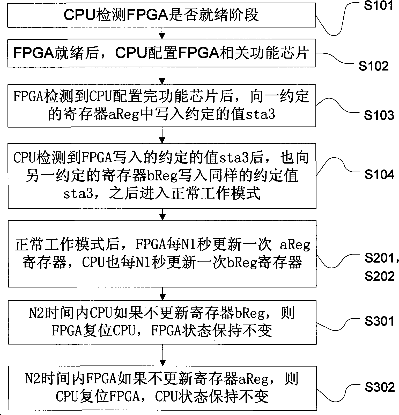
[0028] The present invention provides a method for power-on handshake and mutual monitoring between FPGA and CPU in a communication equipment system, such as figure 1 As shown, it mainly includes three stages: FPGA and CPU power-on initialization handshake process, mutual monitoring after entering normal mode, and FPGA or CPU resetting each other when an abnormal state occurs:

[0029] (1) Initialization process: FPGA and CPU power-on initialization, handshaking process for configuring function chips;

[0030] (2) Normal mode: Mutual "dog feeding" and monitoring after entering the normal mode;

[0031] (3) Abnormal state: the condition for FPGA or CPU to reset the other party.

[0032] first stage, such as figure 1 shown, including the following steps:

[0033] S101, the CPU initializes the system, and configures the bus interface related to th...


PUM


Abstract

The invention discloses a realization method for monitoring a watchdog in an embedded device, which includes the following steps: 1) an FPGA and a CPU respectively write the status information to a register aReg and a register bReg and intersectionally read the status information of the register written by the other party so as to start up a handshake flow and enter into a normal working mode; 2) under the normal working mode, the FPGA and the CPU respectively update the register aReg and the register bReg regularly and intersectionally monitor the updating process of the register written by the other party; when the other party is found not to update the written register, the other party is reset. Through a power-on handshake and monitoring mode by the mutual combination of software and hardware, the FPGA and the CPU in the same system can mutually monitor reset when abnormality occurs. The method also achieves the software rest function by using an external hard reset chip at the same time, thus increasing the reliability of the equipment system operation and realizing the mutual anti-retardation function of the FPGA and the CPU.

Description

technical field [0001] The invention relates to the technical field of communication, and relates to a method for implementing power-on handshake and mutual monitoring between an FPGA module and a CPU module in an embedded system. Background technique [0002] There are basically two ways to monitor the watchdog traditionally in embedded system equipment, (1) use the hardware watchdog to monitor the operation of the software, that is, if the software does not feed the dog within a fixed time (usually implemented by writing a specific register) , and the hardware resets the entire system to play a software fool-proof function; (2) the software watchdog is implemented, and a watchdog task is specially opened to communicate with other tasks in the system within a fixed time. The traditional Windows platform software sees The watchdog generally implements the interaction between the watchdog and the controlled resource (the controlled resource usually exists as a physical proces...

Claims


Application Information

Patent Timeline
Patent Type & Authority Applications(China)
IPC IPC(8): G06F11/00
Inventor 张明生吴饶金
Owner 深圳国人无线通信有限公司
Why Eureka
Try Eureka