
Automatic cable winding and unwinding device for vehicle mounted mast

A retractable device and mast technology, applied in the mechanical and electrical field, can solve the problems of increasing cost, cable breakage, increasing cable burden, etc., and achieve the effect of low cost and simple structure

Active Publication Date: 2010-06-09
CHINA NORTH IND NO 205 RES INST
View PDF2 Cites 0 Cited by
  • Summary
  • Abstract
  • Description
  • Claims
  • Application Information

AI Technical Summary

Problems solved by technology

Among them, the spiral winding method is to coil the cable upward along the mast like a spring. The spring-type cable can be lifted and retracted with the mast. This solution needs to support a steel wire skeleton with proper elasticity in the cable. Hanging and colliding with the mast and twisting itself; the folding take-up method is to arrange the folding frame along the direction of the cable, and lay the cable on the folding frame. The problem is that the folding frame will increase the burden on the cable and the cable will be broken if the cable is repeatedly folded at the same position; the slip ring type is more complicated, and the rotating mechanism is used to wind the cable, and the slip ring is used to ensure that the mast goes up and down during the rotating winding process. It is a good solution for cables with a small number of cores, but for electro-optic hybrid multi-core cables, it needs to be equipped with electric slip rings and optical fiber slip rings, which will greatly increase the cost, increase the complexity and reduce the reliability. In addition, the slip ring will also increase the noise of weak signal transmission

Method used


Image

  • Automatic cable winding and unwinding device for vehicle mounted mast
  • Automatic cable winding and unwinding device for vehicle mounted mast
  • Automatic cable winding and unwinding device for vehicle mounted mast

Examples


Embodiment Construction

[0015] The present invention will be further described below in conjunction with the accompanying drawings and preferred embodiments.

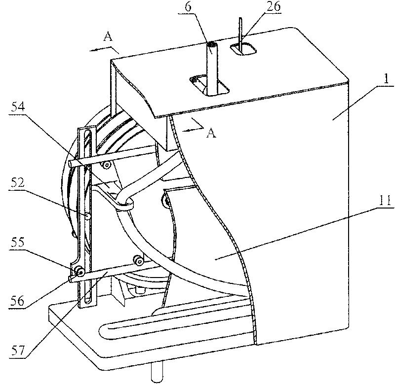
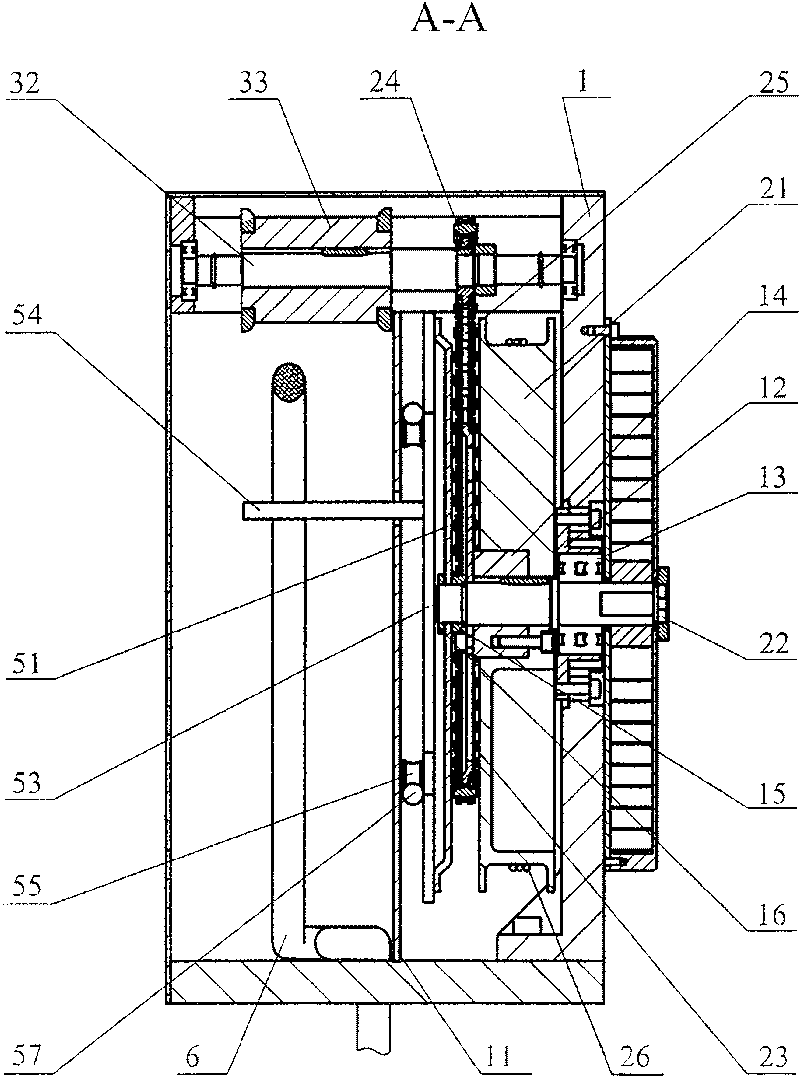
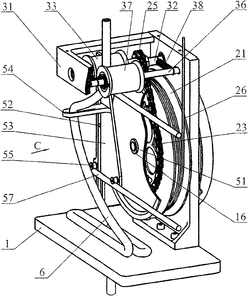
[0016] as figure 1 , figure 2 As shown, the preferred embodiment of the present invention includes a supporting frame body 1 and corresponding connectors and fasteners, a driving mechanism, a dial mechanism, a wire feeding mechanism, and a clockwork mechanism. The support frame body 1 is a rectangular cavity housing with a figure 2 definition) and the height of the partition 11 is lower than the height of the four side walls of the cavity housing, so that three spaces, upper, left and right, are formed in the cavity housing and the partition 11 is provided with a left 1. The long channel for conduction in the space on the right side; the right side wall and bottom plate of the cavity shell are used for load bearing and packaging, and the other side walls and top plate are only used for packaging. The bottom plate is provided with cable hol...


PUM


Abstract

The invention discloses an automatic cable reel device used for a vehicle mast. The device includes a drive mechanism, a dial wheel mechanism, a cable feeding mechanism and a spring mechanism that areall mounted on a supporting framework body. The drive mechanism transmits a drive power to the dial wheel mechanism, the cable feeding mechanism and the spring mechanism simultaneously when the steelwire of the drive mechanism is drawn by the rising of the mast to lead the spring mechanism to store energy by winding; the dial wheel mechanism is driven to transmit the cables to the cable feedingmechanism in orders to release the cables flatly in the mode of clamping; the spring mechanism can release energy when the mast descends and can transfer a power to the cable feeding mechanism and thedial wheel mechanism through the drive mechanism; the cables are collected by the cable feeding mechanism into the supporting framework body and regularly piled through the dial wheel mechanism. Thedevice of the invention has the advantages of a simple structure, low cost, with no twisting, no coiling and no effects on the signal and energy transmission during the process of reeling the cables.

Description

technical field [0001] The invention belongs to the field of mechanical and electrical technology, and mainly relates to an automatic cable retracting device for a vehicle-mounted mast. The automatic cable retracting device is suitable for retracting and retracting multi-channel complex cables with high lift. Background technique [0002] In emergency mobile communications, TV broadcast vehicles, military reconnaissance vehicles, etc., a mast-type lifting telescopic pole (mast for short) is required to lift the optical and electrical equipment to a certain height. There is often a gap between these equipment and the fixed equipment in the vehicle. Complicated cabling (optical cables, electrical cables) connections. In order to prevent these cables from being entangled or twisted during the lifting of the equipment, the cables need to be able to be automatically retracted and retracted as the mast is raised and lowered. During the mast lifting process, the cable should not a...

Claims


Application Information

Patent Timeline
Patent Type & Authority Patents(China)
IPC IPC(8): H02G11/00H02G11/02
Inventor 陈立学刘宇茹志兵陈静王健军
Owner CHINA NORTH IND NO 205 RES INST
Learn More