Air mattress

A technology of inflatable mattresses and inflatable chambers, applied in liquid-filled mattresses, hospital beds, medical science, etc., can solve problems such as collapse and easy slipping of the buttocks, and achieve the effect of preventing collapse

Inactive Publication Date: 2008-09-24
MOLTEN CORPORATION
View PDF1 Cites 7 Cited by
  • Summary
  • Abstract
  • Description
  • Claims
  • Application Information

AI Technical Summary

Problems solved by technology

At this time, if the internal pressure drops too low, there is a danger of collapse
[0007] In addition, in adopting the above-mentioned patent document 1 figure 2 and Patent Document 2 Figure 5 In the case of the end structure shown in , if the air is filled, the side will expand spherically, so if you sit on the end seat when you get up from this air mattress, there is a problem that the buttocks will easily slip off.

Method used


Image

  • Air mattress
  • Air mattress
  • Air mattress

Examples


Embodiment Construction

[0025] Embodiments of the invention of the present application will be described in detail below with reference to the accompanying drawings.

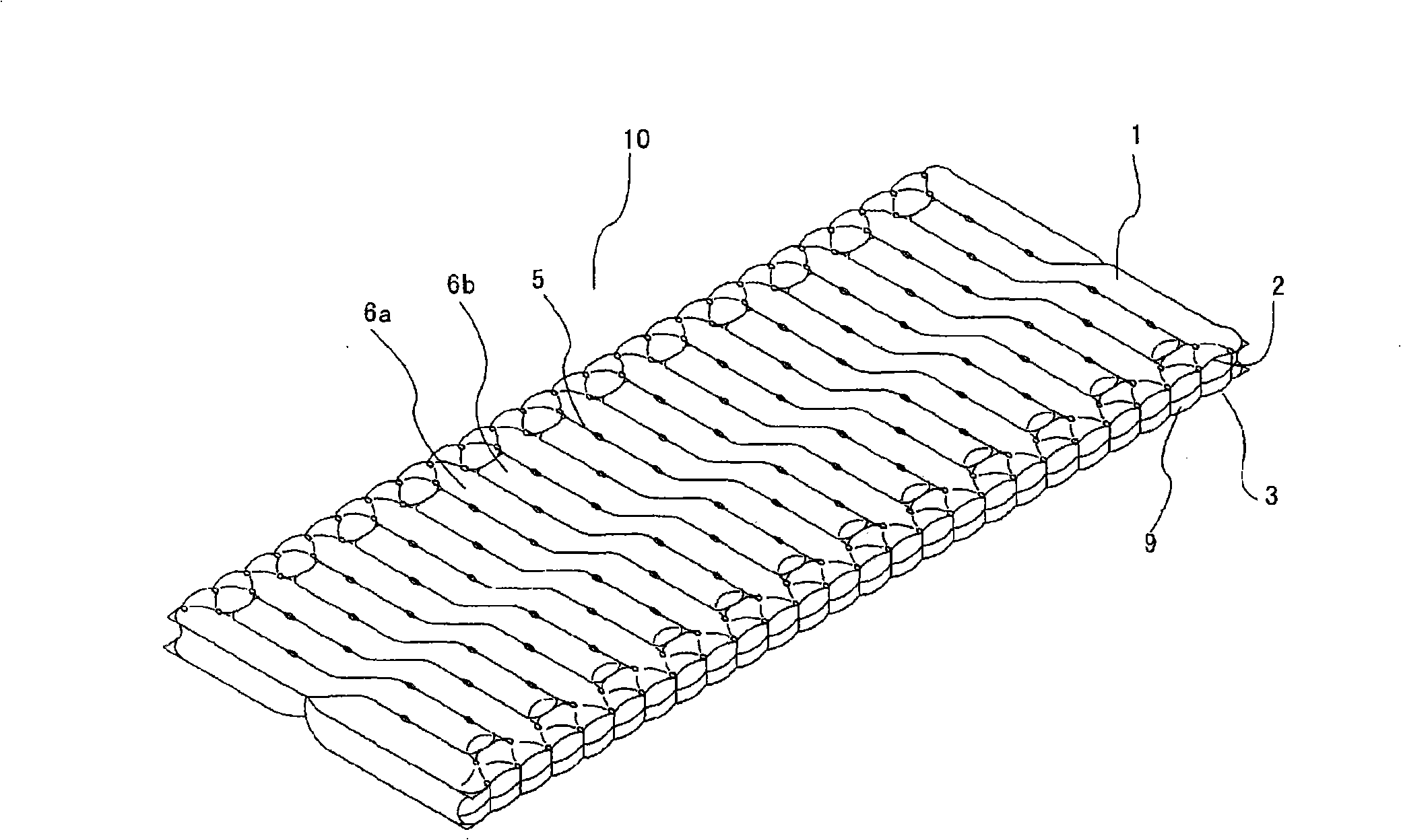
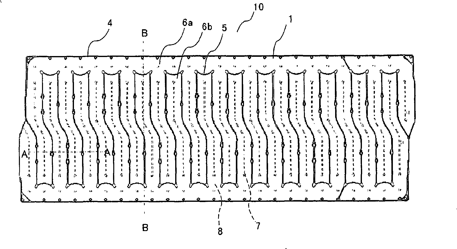
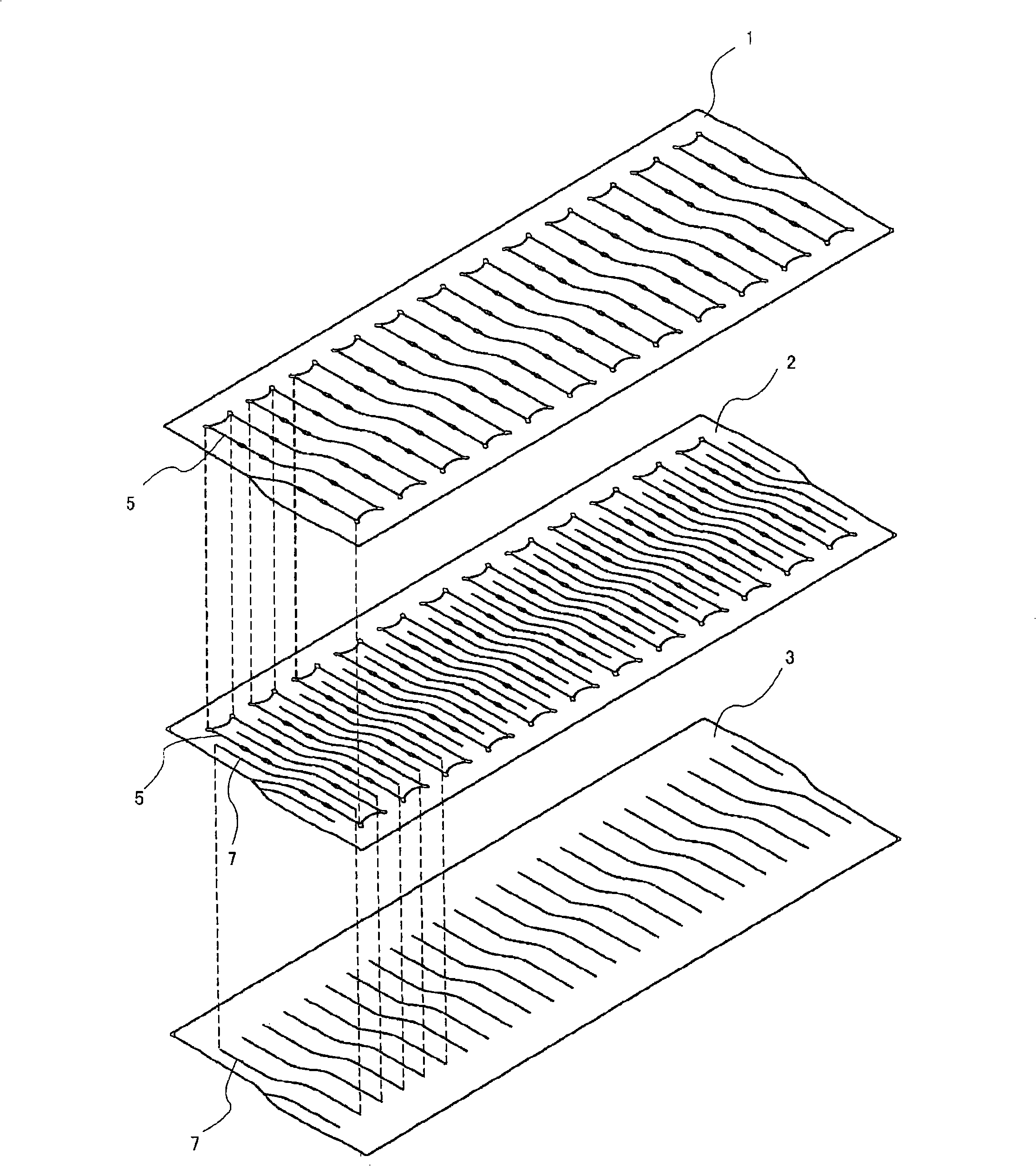
[0026] figure 1 It is a perspective view of an air mattress according to an embodiment of the invention of the present application, figure 2 for top view, image 3 It is a schematic perspective view showing the bonding relationship of the first to third ply sheets, Figure 4 for figure 2 A schematic sectional view of line A-A in Figure 5 for figure 2 A schematic sectional view of line B-B in . In each figure, the same or corresponding parts are indicated by the same symbols.

[0027] The air mattress 10 of the present embodiment has 3 pieces of flexible rectangular plies stacked, which are the first ply 1, the second ply 2, and the third ply 3 from top to bottom. The surrounding part 4 is connected.

[0028] A first adhesive part 5 is bonded between the first ply 1 and the second ply 2, thereby forming the first layer system ...


PUM


Abstract

An air mattress capable of preventing its bottoming from occurring in an integrated mattress. The air mattress comprises three sheets (1 to 3) mutually overlapped with each other, adhered to each other at their peripheral parts, and brought into a sealed state. First layer air cells (6a, 6b) formed of tubular air cells in the lateral direction by the first and second sheets (1, 2). The second layer air cells (8) are formed of tubular air cells formed in the lateral direction by the second and third sheets (2, 3). The first layer air cells (6a, 6b) and the second layer air cells (8) are arranged so as to be displaced from each other in the longitudinal direction.

Description

technical field [0001] The invention relates to an air mattress with comfort and safety. Background technique [0002] In the prior art, as an air mattress, an integrated mattress is mostly a structure formed by welding and welding the ends of the inner and outer layers of the air mattress (for example, refer to the patent document [0003] 1. Patent Document 2). [0004] Patent Document 1: JP Unexamined Publication No. 7-308242 ( figure 2 ) [0005] Patent Document 2: JP Patent No. 3290159 ( Figure 5 ) [0006] When the above-mentioned air mattress is used to prevent decubitus ulcers, the internal pressure of the air mattress is usually controlled to a low level to form a good body pressure distribution performance. At this time, if the internal pressure drops too low, there is a risk of collapse. [0007] In addition, in adopting the above-mentioned patent document 1 figure 2 and Patent Document 2 Figure 5 In the case of the end portion structure shown in , if th...

Claims


Application Information

Patent Timeline
Patent Type & Authority Applications(China)
IPC IPC(8): A47C27/10
CPCA47C27/087A61G7/05776A47C27/081A47C27/10
Inventor 大西洋浜俊二冈崎秀和
Owner MOLTEN CORPORATION
Why Eureka
Try Eureka