Separator assembly

A technology for separating components and airflow, which is applied in the direction of cyclone device, immiscible liquid separation, sediment separation by centrifugal force, etc. It can solve the problems of high operating cost and low efficiency, and achieve the effect of improving separation characteristics

Active Publication Date: 2008-09-24
PARKER HANNIFIN CORP
View PDF3 Cites 16 Cited by
  • Summary
  • Abstract
  • Description
  • Claims
  • Application Information

AI Technical Summary

Problems solved by technology

Generally, in compressed gas systems, the higher the pressure drop across the separation components, the less efficient the system is and the more expensive the system is to operate

Method used


Image

  • Separator assembly
  • Separator assembly
  • Separator assembly

Examples


Embodiment Construction

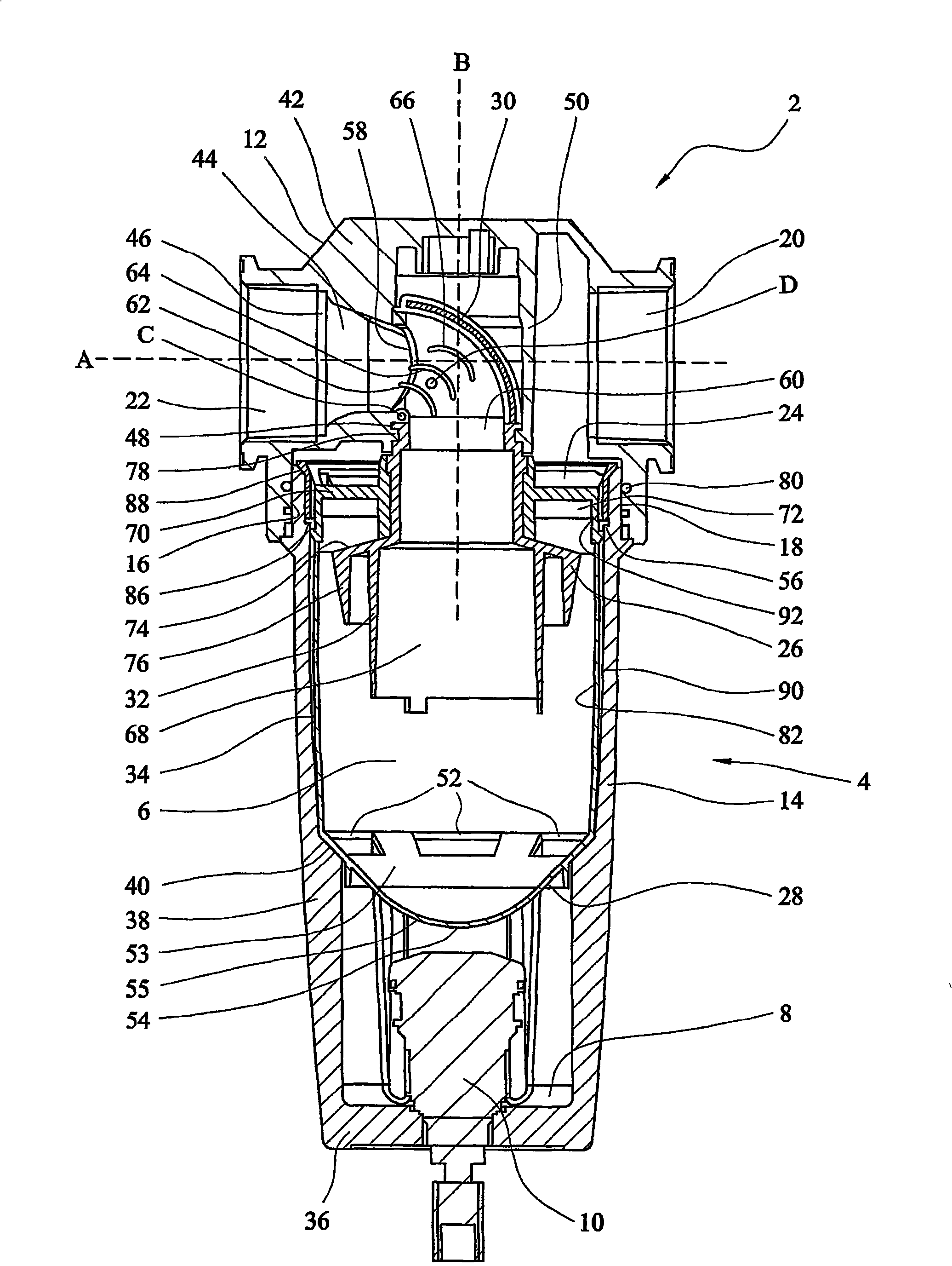
[0060] Referring to the drawings, FIG. 1 shows a separation assembly 2 comprising a housing 4 defining an internal volume 6 . The housing 4 comprises a head 12 and a body portion 14 which can be connected to each other by mating threads at their joint faces 16 , 18 . The housing 4 also includes: an inlet 20 and an outlet 22 in the head 12 for gas to enter and exit the separation assembly 2; a reservoir 8 at a second end of the housing opposite the first end; and a liquid outlet 10. The separation assembly also includes a flow guide 24 , a deflector 26 , a shield 28 , and a flow channel arrangement 30 including a conduit portion 32 , all located within the body portion 14 of the housing 4 .

[0061] The head 12 and body part 14 are constructed of a metallic material, in particular aluminum or an alloy thereof. They may be formed by machining or by techniques such as casting.

[0062] Body portion 14 includes: a cylindrical wall 34; an end wall 36 at one end of cylindrical wa...


PUM


Abstract

A separator assembly (2) for removing material that is entrained in a gas stream. The separator assembly (2) comprises a housing having (4) inlet (20) and outlet (22) ports for the gas from which material is to be removed. The inlet (20) and outlet (22) ports are located toward the upper end of the housing. A flow director (24) is positioned so that gas flowing into the housing (4) flows over the flow director (24) so that the incoming gas is made to follow a generally helical path within the housing. The separator assembly (2) also comprises a shield (28) which extends across the housing towards the lower end thereof so as to leave a collection space (8) between it and the lower end in which material that is separated from the gas stream can collect. There is at least one opening (52) in or around the shield through which the material can flow past the shield into the collection space (8). The face of the shield (28) which is directed towards the upper end of the housing is bowl-shaped .

Description

technical field [0001] The present invention relates to a separation assembly for removing substances such as liquids in the form of aerosols entrained in a gas flow. Background technique [0002] It may be necessary to remove entrainment from a gas stream to ensure that the gas is sufficiently clean for subsequent applications, or to minimize the adverse effects of impurities on components of the system. For example, concentrated oil may need to be removed to minimize chemical contamination and buildup on valves that could lead to valve failure, and solid particulate matter may need to be removed to minimize wear. Additionally, liquids such as water droplets may need to be removed from the gas stream in order to minimize the fouling load on downstream filters. [0003] Separation assemblies for use in compressed gas systems are known that are designed to remove entrained material from a gas stream prior to downstream application. Such a separation assembly includes a wate...

Claims


Application Information

Patent Timeline
Patent Type & Authority Applications(China)
IPC IPC(8): B01D17/02B01D21/26B04C5/13B04C5/14B04C5/06B04C5/103
Inventor B·莱恩S·比特尔R·特罗斯达勒
Owner PARKER HANNIFIN CORP
Why Eureka
Try Eureka