Circuit, shrink fixing and regulation method

A circuit and intermediate circuit technology, applied to the circuit, can solve problems such as oversize, and achieve the effects of increasing load, optimizing size, and optimizing overload protection

Inactive Publication Date: 2008-09-24
FRANZ HAIMER MASCHINENBAU KG
View PDF2 Cites 4 Cited by
  • Summary
  • Abstract
  • Description
  • Claims
  • Application Information

AI Technical Summary

Problems solved by technology

This would oversize the module that is then connected to the measuring device to measure the control parameters

Method used


Image

  • Circuit, shrink fixing and regulation method
  • Circuit, shrink fixing and regulation method

Examples


Embodiment Construction

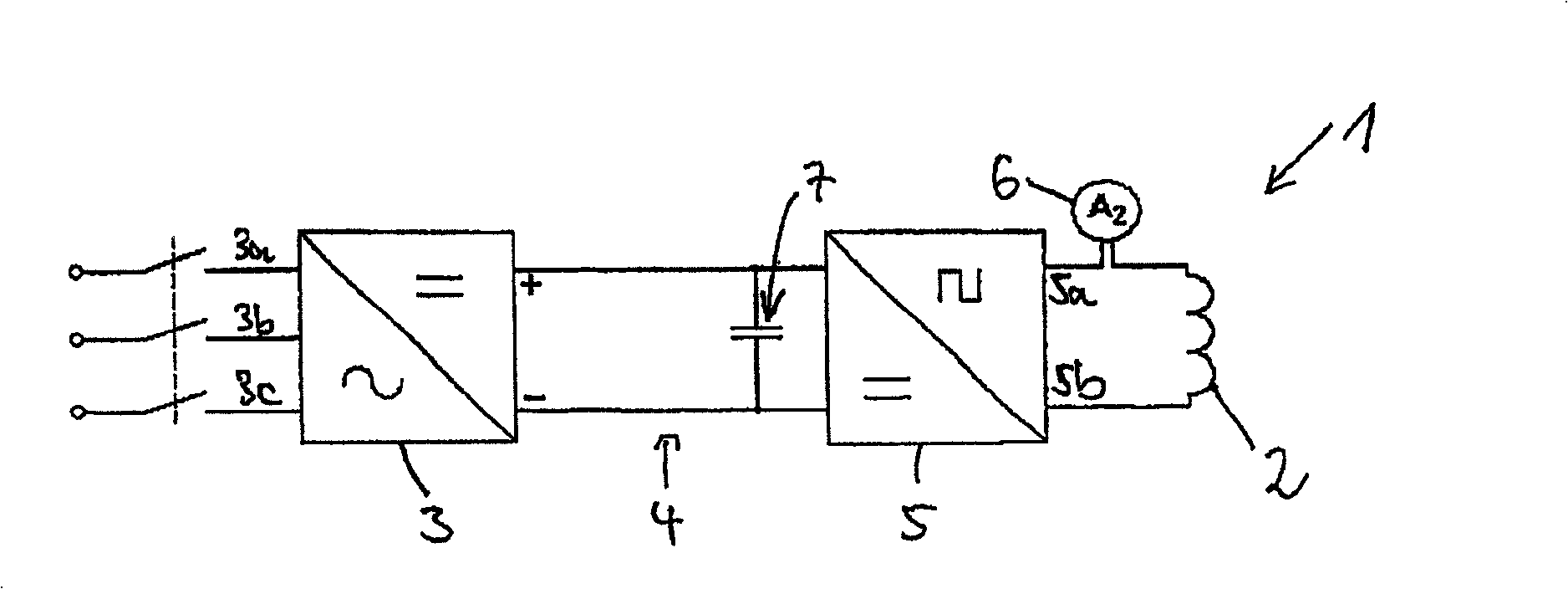
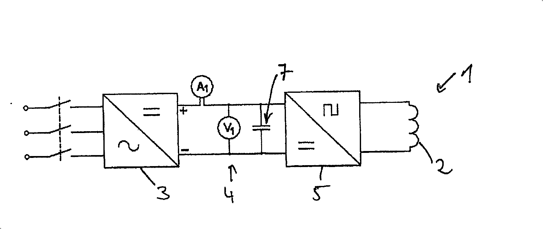
[0033] exist figure 1 A circuit 1 for controlling the power supply to an induction coil 2 according to the invention is shown in . This circuit is equipped on a circuit board and thus constitutes a control circuit board for supplying power to the coil 2 .

[0034] In particular, the induction coil 2 acts as a shrink fitting of the heating tool. An induction coil 2 generates an alternating electromagnetic field to which the shrink fit is connected. Heat is generated by the Eddy current generated in the shrink fitting and / or by changing the magnetization of the shrink fitting made of ferromagnetic material, so that the shrink fitting expands so that the tool can be inserted.

[0035] During the heating process, it is necessary to supply the induction coil 2 with a maximum power as constant as possible, taking into account the maximum permissible load of the components. Of course, on the one hand the maximum load limits of the induction coil 2 and the power electronics must be...


PUM


Abstract

A circuit 1 for controlling the supply of electrical power to an induction coil 2, in particular to an induction coil 2 for heating a shrink fixing for tools, comprises a rectifier 3 having an input 3a, 3b, 3c for feeding in an input power and having a rectifier output. In addition, the circuit 1 has an inverter 5 for outputting an AC voltage having an input and an inverter output 5a, 5b for connection to the induction coil 2, an intermediate circuit 4 for connecting the rectifier 3 to the inverter 5, and a regulating unit for regulating the power supply to the induction coil 2. A measuring apparatus 6 for measuring a current A2 as input variable for the regulating unit is connected to the output side of the inverter 5.; A corresponding method for regulating the power supply to the induction coil 2 comprises a regulation step, in which the current A2 supplied to the induction coil 2 is used as input variable for the regulation of the power supply to the induction coil 2.

Description

technical field [0001] The present application relates to a circuit for controlling power supplied to an induction coil, more particularly an induction coil for heating a shrink fitting of a tool, comprising a rectifier having an input delivering input power and a rectifier output; for outputting an AC-voltage Inverter, the inverter includes an input and an inverter output to connect the induction coil; the intermediate circuit connecting the rectifier to the inverter and the control unit used to control the power given to the induction coil; used to deliver power to the induction coil Coil power supply unit. In addition, the present application also relates to a shrink fitting of a tool, including an induction coil for heating the shrink fitting by generating an Eddy current and / or generating heat through a magnetic change, and to a method of controlling the power supply to the induction coil, more particularly a An induction coil for heating a shrink fitting of a tool, the ...

Claims


Application Information

Patent Timeline
Patent Type & Authority Applications(China)
IPC IPC(8): H05B6/06H05B6/14
CPCH05B6/14H05B6/06
Inventor 弗兰斯·海默尔吉瑞·福特
Owner FRANZ HAIMER MASCHINENBAU KG
Why Eureka
Try Eureka