
Control method for equilibrium operation of converter dust-removing flue cooling fan

A cooling fan and balanced control technology, which is applied in the direction of using electric methods for temperature control and manufacturing converters, etc., can solve the problems of low power-on duration of the backup fan motor, unbalanced fan motor running time, and short fan motor running time. To achieve the effect of saving investment, reducing the continuous rate of power supply and improving the operation rate

Inactive Publication Date: 2008-10-01
BAOSHAN IRON & STEEL CO LTD
View PDF0 Cites 14 Cited by
  • Summary
  • Abstract
  • Description
  • Claims
  • Application Information

AI Technical Summary

Problems solved by technology

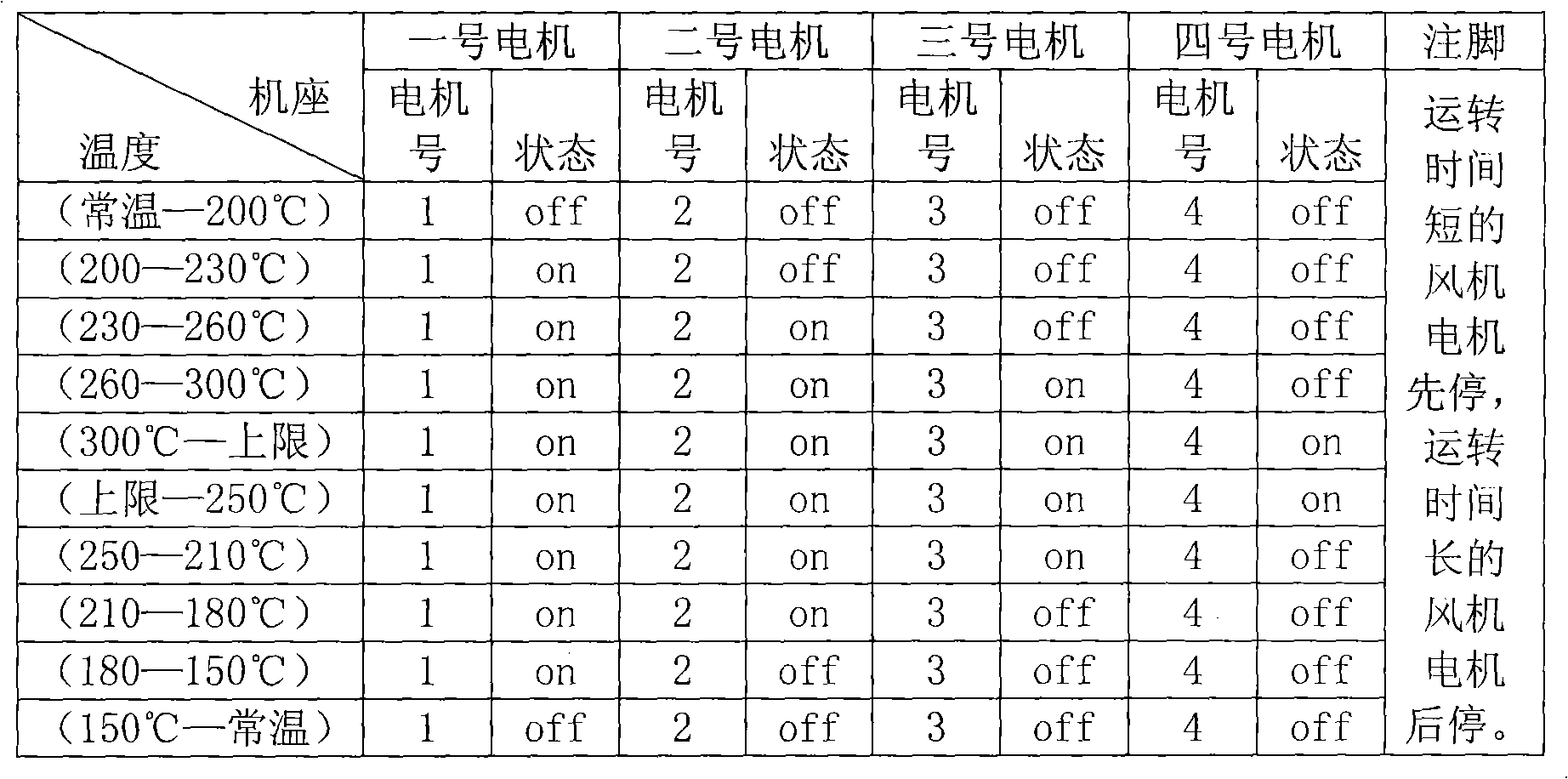
[0009] (1) The running time of the fan motor at the low-temperature end is long, and the running time of the fan motor at the high-temperature section is short; the fan motor is started first and then stopped, and the running time of the fan motors in the operation group is extremely unbalanced
[0010] (2) Usually, the standby fan motor of No. 4 frame is in a long-term standby state at the temperature of the dust removal flue, and it can only be put into operation when one of the other three motors fails, so the standby fan motor and other fan motors in the operation group more unbalanced than running time
[0011] (3) If it is considered that the change of the controlled object fluctuates in a certain interval, the motor running on this interval will start frequently, and the service life of the motor will be affected
[0012] (4) The power-on duration of the spare fan motor is too low

Method used


Image

  • Control method for equilibrium operation of converter dust-removing flue cooling fan
  • Control method for equilibrium operation of converter dust-removing flue cooling fan
  • Control method for equilibrium operation of converter dust-removing flue cooling fan

Examples


Embodiment Construction

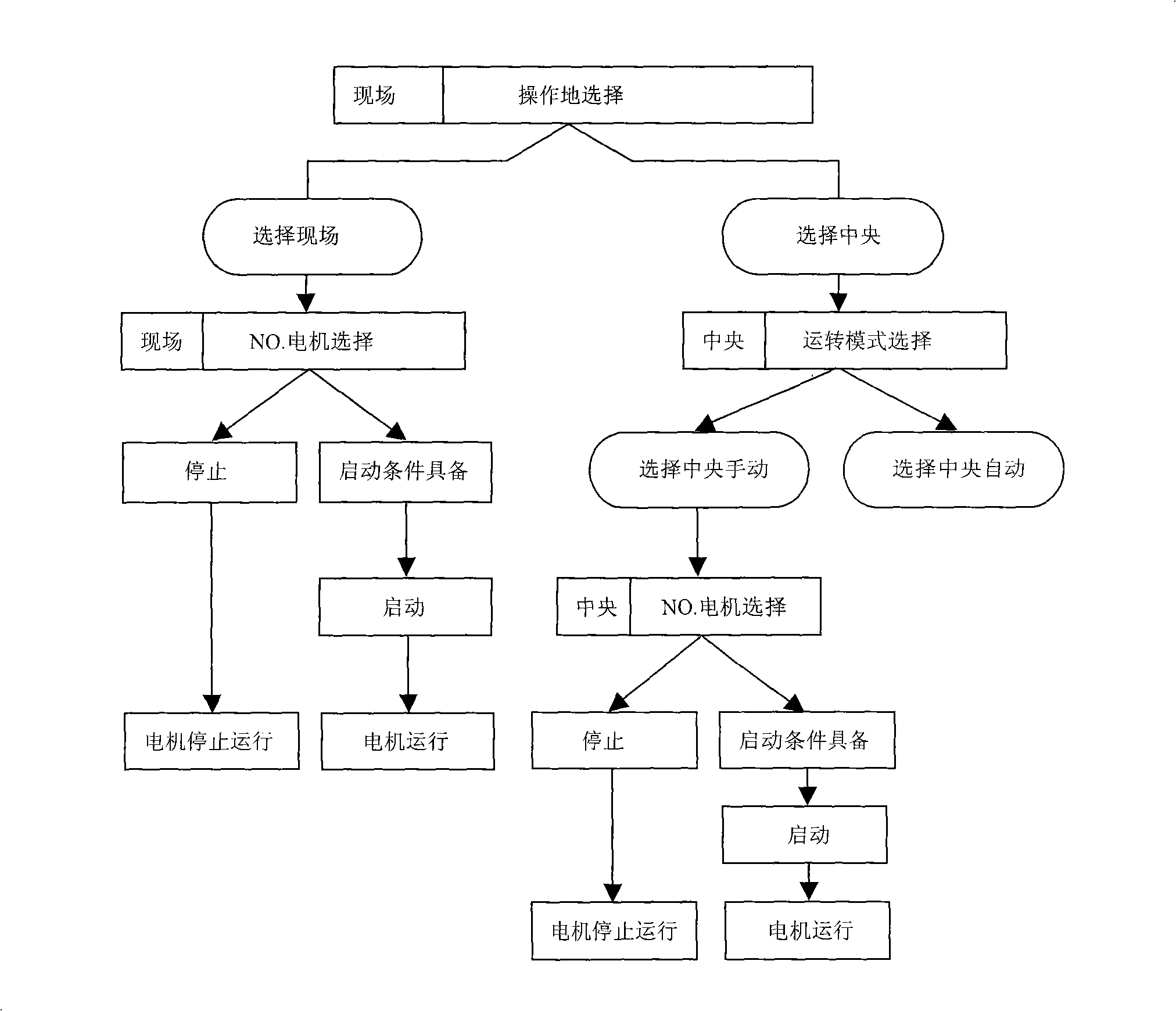
[0031] The present invention will be further described below in conjunction with the accompanying drawings and specific embodiments.

[0032] see figure 1 , a converter dust removal flue cooling fan operation control method, using the site manual, central (remote) manual, central (remote) automatic three control modes. The on-site manual control mode is used for starting and stopping the motors in the case of on-site maintenance and on-site testing; the central (remote) manual control mode is used for manually starting and stopping each motor on the human-machine interface (HMI); the central (remote) automatic control The method is to automatically start and stop a certain motor in the group according to the change of the controlled object.

[0033] Each motor has an on-site operation box, and there is a selection switch for on-site and central on the operation box. The on-site operation enjoys the highest priority. Once the operation right of a fault-free motor is switched f...


PUM


Abstract

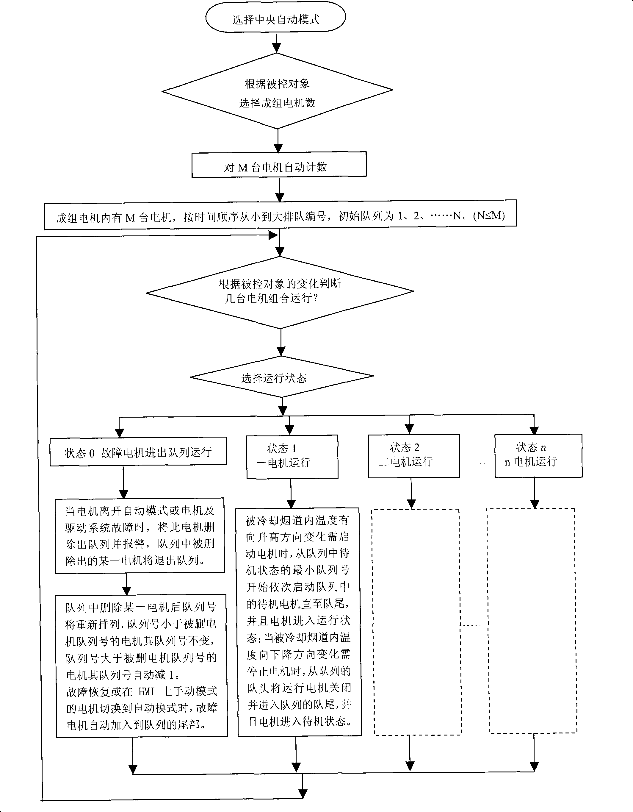
The invention discloses a method for evenly controlling the running of cooling fan in convertor dust removal flue, the control method comprises the steps of: orderly starting up engines in a state of standby in the queue from the minimum queue number to the end of the queue and leading the engines to the running state, when the temperature in the cooling flue raises and the engines are in need of starting-up; shutting down the running engines from the head of running queue, enabling the end of queue entering the queue to become a new end of queue and leading the engines to the standby state, when the temperature in the cooling flue drops and the engines are in need of shutdown. The invention automatically controls the engines according to the principal first-startup-first-shutdown, the engine running in a long time has the priority of shutdown so that each engine runs evenly; under the condition of fluctuating interval temperature, each engine can averagely share the times of startup and shutdown, which can prolong the service life of the apparatus and improve the dependability. The invention can be suitable for the apparatus including other controlled objects in need of adjustment and using a plurality of engines.

Description

technical field [0001] The invention relates to a balanced control method for the operation of a converter dust removal flue cooling fan. Background technique [0002] According to the technological requirements of the converter smelting, the primary high-temperature dusty flue gas discharged from the furnace mouth is cooled to 620°C by the vaporization flue system, and then enters the bag filter after being cooled by the forced air cooler. In order to control the temperature of the flue gas entering the bag filter at about 320°C, it is necessary to carry out forced cooling in the forced air cooler, which generally uses four fans for cooling. [0003] The cooling fan for the dust removal flue of the converter adopts a four-fan group as a backup operation queue. The operation of the motor unit adopts three control methods: on-site manual, central (remote) manual, and central (remote) automatic. The on-site manual control mode is used for starting and stopping the motors in ...

Claims


Application Information

Patent Timeline
IPC IPC(8): C21C5/38G05D23/19
Inventor 汤德明张健陈洁方杰
Owner BAOSHAN IRON & STEEL CO LTD
Learn More