Bootstrap type hydraulic drive limiting slip differential

A limited-slip differential and hydraulic drive technology, applied in the direction of differential transmission, transmission, belt/chain/gear, etc., can solve the problem of reduced driving torque of half-axle wheels, low locking coefficient, and steering resistance Large and other problems, to achieve the effect of improving the locking coefficient, increasing internal friction, and small size

Inactive Publication Date: 2008-10-01
BEIJING JIAOTONG UNIV
View PDF0 Cites 13 Cited by
  • Summary
  • Abstract
  • Description
  • Claims
  • Application Information

AI Technical Summary

Problems solved by technology

However, under the condition that the unilateral drive wheel is still slipping, the drive torque to the axle wheel is also significantly reduced.
Compared with the speed-sensitive limited-slip differential, the structure of the torque-sensitive limited-slip differential is slightly simpler, but the steering resistance is larger
[0007] There is also a variable transmission ratio differential. This type of differential has been used by Timken Company of the United States since the 1930s, but its locking coefficient is low, changing between 1.25 and 1.5, which cannot meet the requirements of off-road vehicles; The three-stage variable transmission ratio differential invented by Professor Wang Xiaochun of Beijing Jiaotong University breaks through the limitation of the traditional single-stage variable transmission ratio differential. By adopting a special tooth surface design, the three-stage variable transmission ratio differential The locking coefficient has reached 3.0~3.5, which can meet the requirements of commercial vehicles

Method used


Image

  • Bootstrap type hydraulic drive limiting slip differential
  • Bootstrap type hydraulic drive limiting slip differential
  • Bootstrap type hydraulic drive limiting slip differential

Examples


Embodiment Construction

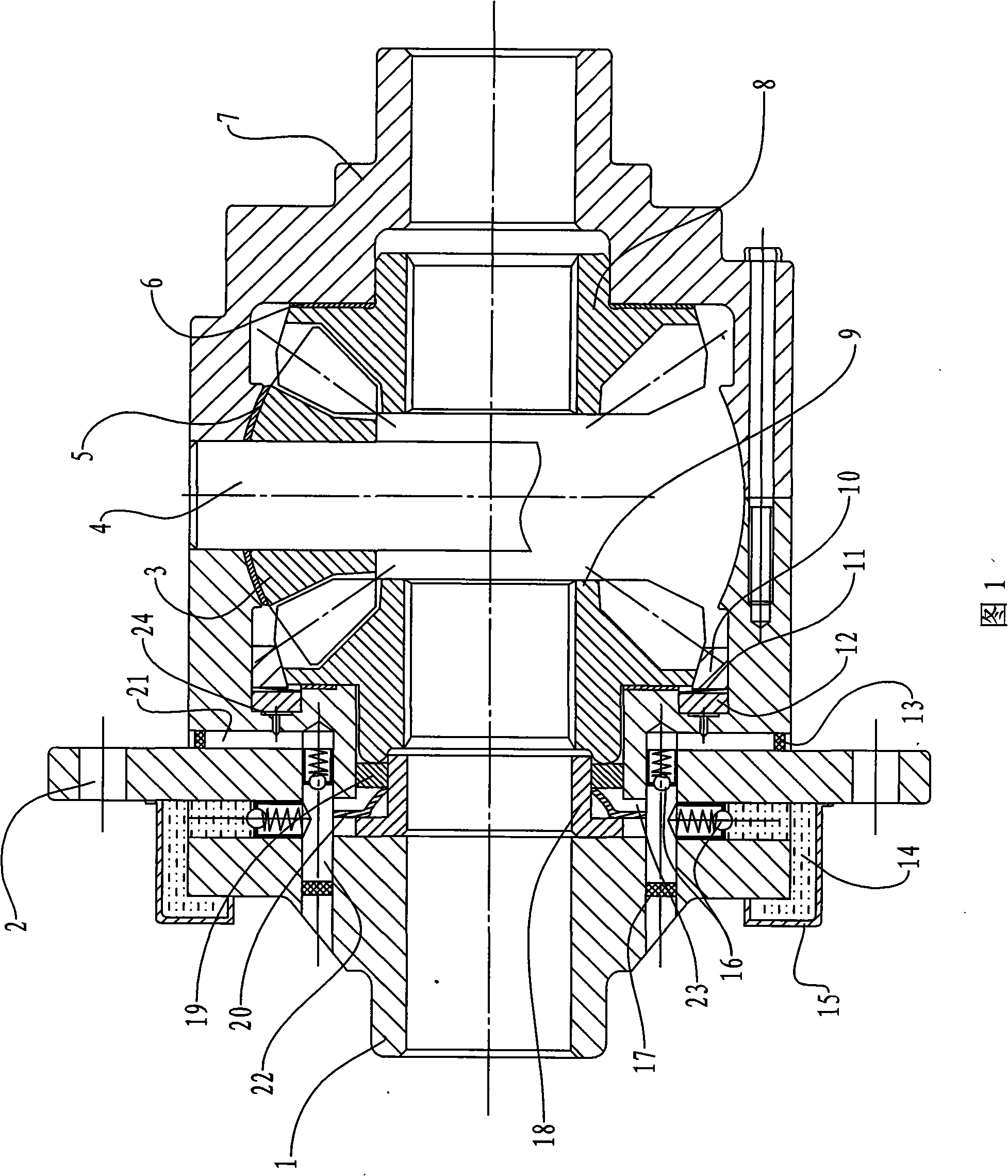
[0027] The present invention will be described in further detail below in conjunction with accompanying drawing:

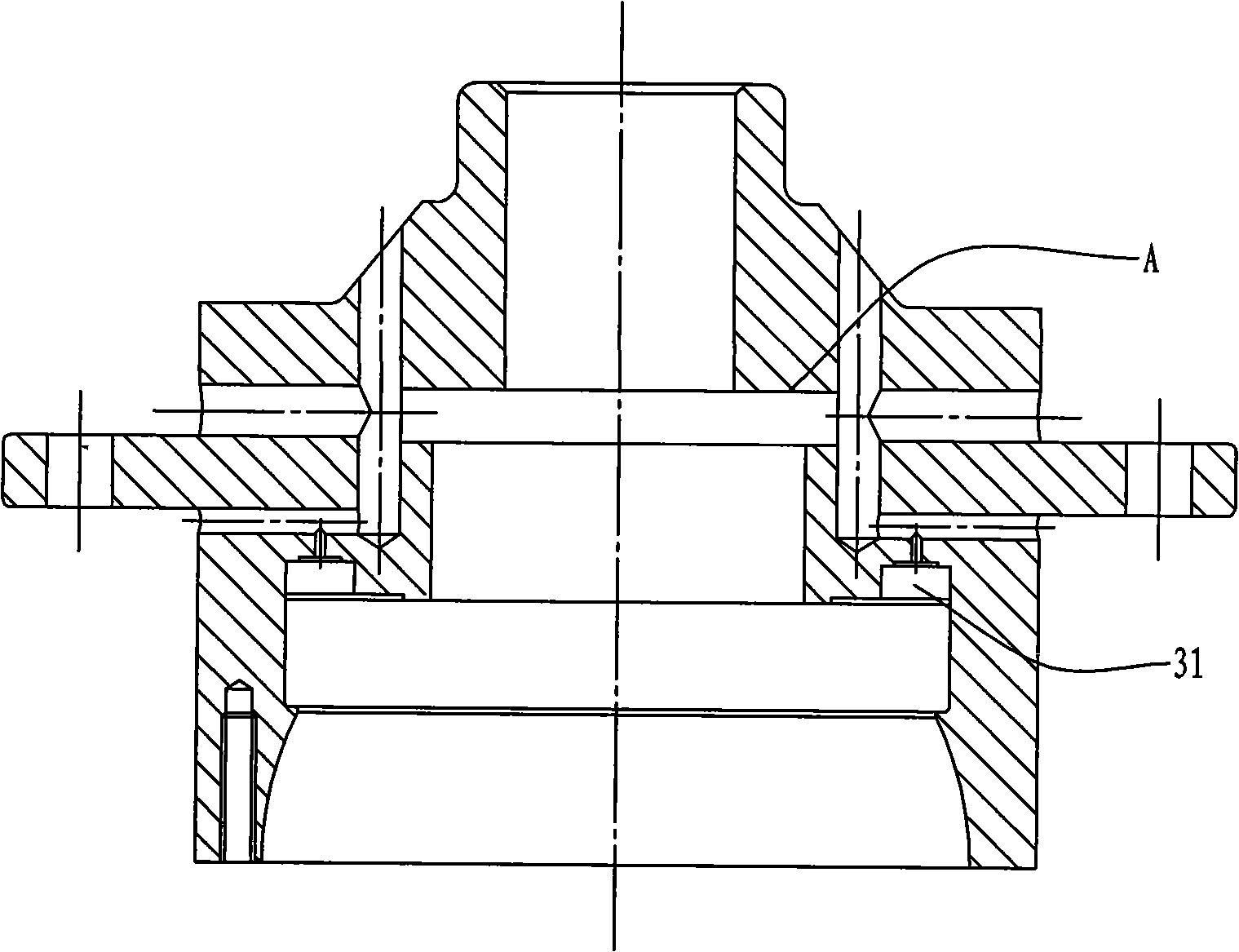
[0028] For the specific structure of this implementation example, refer to FIG. 1 . A bootstrap hydraulically driven limited-slip differential of the present invention includes left and right housings and a differential assembly installed therein, on the A end face of the left housing 1 of the differential and the non-tooth end face of the side gear 9 The L-shaped pump sleeve 18 coaxially installed between them, the return spring 20, the piston 19, the piston 19 and the L-shaped pump sleeve 18 have a clearance fit, the piston 19 has a clearance fit with the left housing 1 of the differential, and the L-shaped pump sleeve 18 , a return spring 20, and a piston 19 constitute a piston pump; an oil inlet passage 14 and an oil outlet passage 21 are opened in the differential left housing 1, and between the oil inlet passage 14 and the pressure chamber 22, between the pr...


PUM


Abstract

A self-booting type hydro dynamic drive slip limit differential gear includes a left and a right casings and a differential gear assembly thereof; an L-shape pump case (18), a reset spring (20), a piston (19) are arranged between a end face (A) of the differential gear left casing (1) and a non-gear end face of the face gear (9), which compose a piston pump; an oil in duct (14), an oil out duct (21) are provided in the left case of the differential gear, and a uni-directional valve (16) is arranged between the oil in duct and a pressure chamber (23), the pressure chamber and the oil out duct; an annular oil cap is arranged on the case of the differential gear, which forms an oil in tank with the left case of the differential gear. The invention has simple structure, small volume, light weight etc., which automatically adjusts the locking capacity of the differential gear according to the speed difference between the driving wheels, reduces the curve resistance and the abrasion of the vehicles to be suitable for all vehicles.

Description

[0001] Field [0002] The invention relates to a limited-slip differential for wheeled vehicles, in particular to a speed-sensitive limited-slip differential driven by a built-in piston pump to drive an annular piston and a friction ring. Background technique [0003] As we all know, when the vehicle is turning, the speed of the outer drive wheel must be greater than the speed of the inner drive wheel, and the basic function of the differential is here. The differential is located in the middle of the two drive wheels, and the drive wheels are coupled through two half shafts driven by side gears. The side gears are connected together by planetary gears. When the car is running straight, the planetary gears only revolve around their axes and do not rotate around their axes, thus driving the two side gears to rotate at the same speed. But when the car turns, the planetary gears also rotate around their axes while revolving, which makes the two side gears rotate at different sp...

Claims


Application Information

Patent Timeline
Patent Type & Authority Applications(China)
IPC IPC(8): F16H48/26F16H48/06
Inventor 程云建王小椿
Owner BEIJING JIAOTONG UNIV
Why Eureka
Try Eureka