Des-backbone winding ring chucking appliance for optical fiber gyroscope without rise optical fiber ring

A technology of fiber optic gyroscope and fiber optic ring, which is applied in the direction of Sagnac effect gyroscope, etc., can solve the problems of fiber optic coil stress, uneven temperature field distribution, coil extrusion, unreasonable heat flow direction of conduction, etc., and achieve miniaturization , good vibration performance and compact structure

Inactive Publication Date: 2008-10-01
BEIHANG UNIV
View PDF0 Cites 25 Cited by
  • Summary
  • Abstract
  • Description
  • Claims
  • Application Information

AI Technical Summary

Problems solved by technology

[0004] The current optical fiber coil structure is mostly "I"-shaped structure. The skeleton structure on the upper and lower sides and in the middle will constrain the optical fiber coil. When the vibration conditions and

Method used


Image

  • Des-backbone winding ring chucking appliance for optical fiber gyroscope without rise optical fiber ring
  • Des-backbone winding ring chucking appliance for optical fiber gyroscope without rise optical fiber ring
  • Des-backbone winding ring chucking appliance for optical fiber gyroscope without rise optical fiber ring

Examples


Embodiment Construction

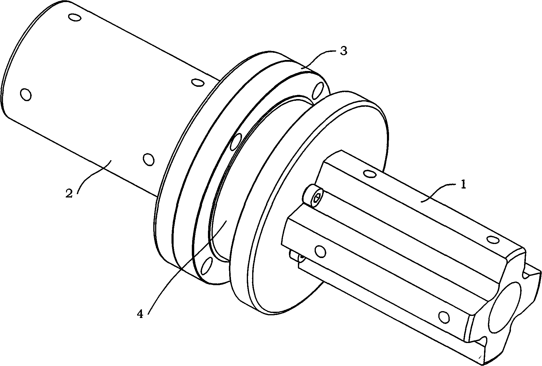
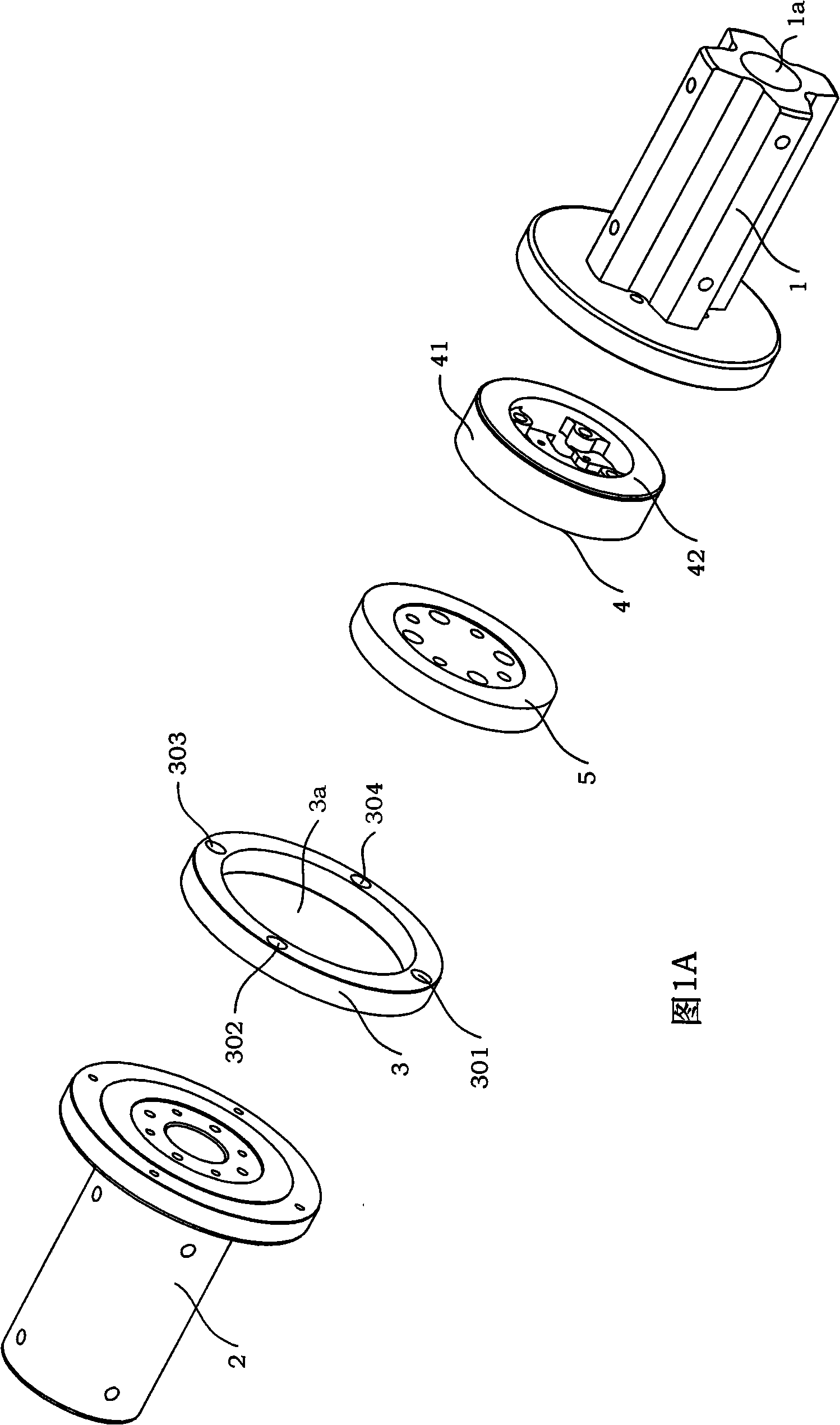
[0028] see figure 1 , figure 1 As shown in A, the present invention is a frame-free ring clamp for fiber optic rings without an upper edge. The frame-free ring clamp includes a ring A clamp 1, a ring B clamp 2, a ring 3, an optical fiber Ring 4, off-shelf ring 5, (see figure 1 Shown in A) From left to right, the layout is the ring B clamp 2, the ring 3, the detachment ring 5, the optical fiber ring 4, and the ring A clamp 1. The ring 3 is installed on the outer ring of the end face 2b of the ring B fixture 2; the detached ring 5 is set in the ring 3 and installed on the D boss 21 of the ring B fixture 2; one end of the optical fiber ring 4 The other end of the optical fiber ring 4 is in contact with the B cavity 11 of the ring A clamp 1; the ring A clamp 1 and the ring B clamp 2 are connected by screws.

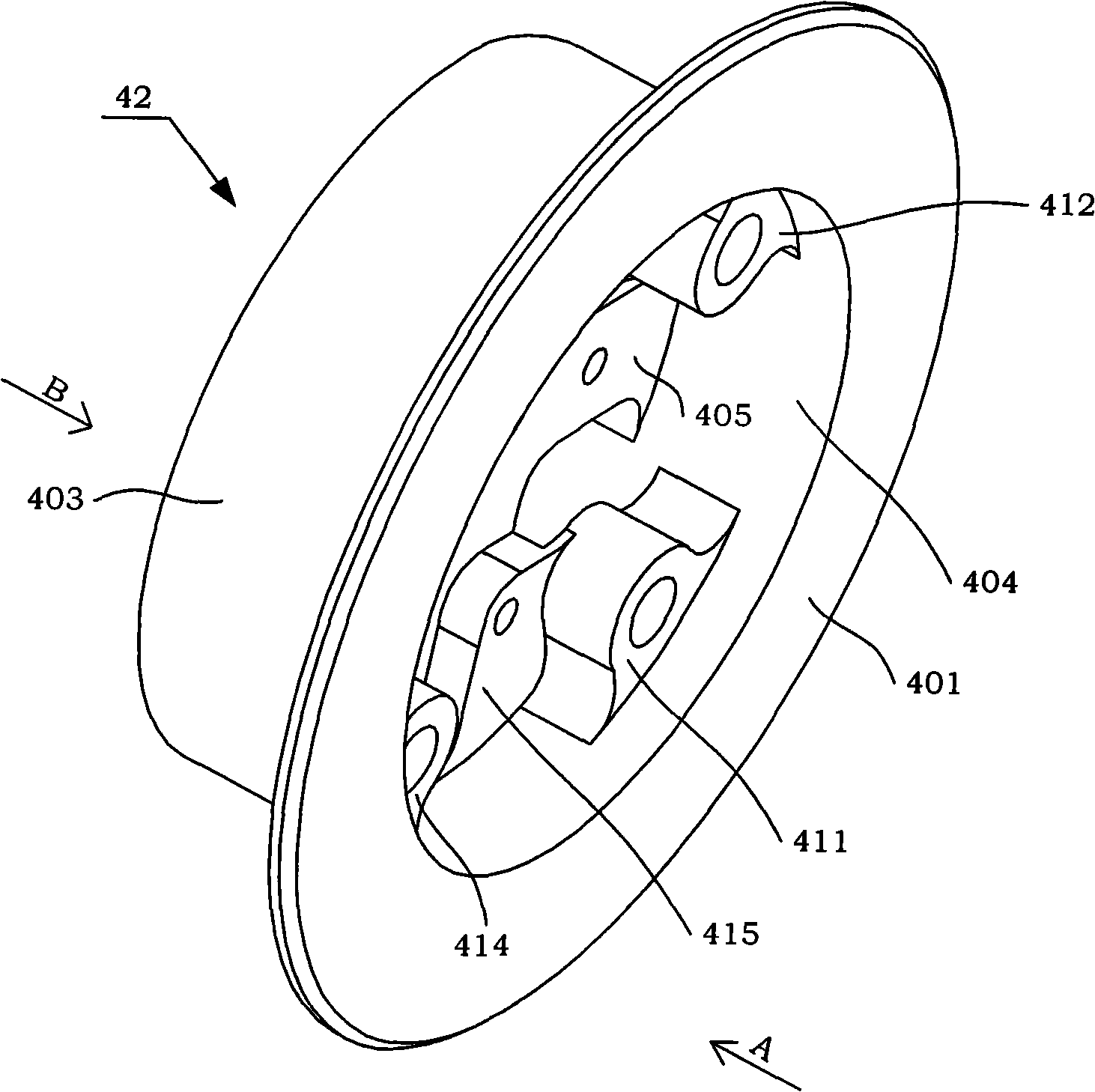
[0029] see figure 1 A. figure 2 As shown, the optical fiber ring 4 is composed of an optical fiber coil 41 and an optical fiber skeleton 42. The optical fiber skeleton ...


PUM


Abstract

The invention discloses a de-framing coil clamp for non-upper edge optic fiber ring of optic fiber gyroscope, composed of a coil A clamp (1), a coil B clamp (2), a round ring (3), a optic fiber ring (4), and a de-framing ring (5), the round ring (3) is installed on outer ring of end face (2b) of the coil B clamp (2), the de-framing ring (5) is sleeved in the round ring (3), and installed on D lug boss (21) of the coil B clamp (2); one end of the optic fiber ring (4) contacts with A end face (5) of the de-framing ring (5), the other end of the optic fiber ring (4) contacts with B recessed cavity (11) of the coil A clamp (1); the coil A clamp (1) is connected with the coil B clamp (2) via screws. The upper part of optic fiber frame (42) of optic fiber (4) according to the invention are in free state without being limited by the upper edge, and being extruded under condition of vibration or temperature change, meanwhile, the lower part of the optic fiber coil (41) contacts with the optic fiber frame (42) to realize supporting effect and distribute the temperature gradient along the axle line direction.

Description

technical field [0001] The invention relates to the technical fields of optical fiber sensing, optical fiber gyroscope and orbiting, and is especially suitable for the application field of inertial navigation technology with small volume and harsh temperature conditions. Background technique [0002] Optical fiber gyroscope is a sensor used to detect the angular rate of carrier motion. It uses the optical Sagnac effect and optical fiber transmission principle to overcome a series of shortcomings of electromechanical gyroscope and laser gyroscope. It has all solid state, high reliability, dynamic With the advantages of large range, wide frequency band, small size and good vibration performance, it is widely used in aerospace, aviation, navigation, oil exploration and other fields. [0003] Optical fiber gyroscope is an opto-mechanical-electrical integration sensor. In the case of higher and higher precision requirements, the influence of vibration and temperature on performan...

Claims


Application Information

Patent Timeline
IPC IPC(8): G01C19/72
Inventor 贾明宋凝芳张春熹徐宏杰
Owner BEIHANG UNIV
Why Eureka
Try Eureka