
Differential scanning calorimeter

A calorimeter and differential technology, applied in the field of differential scanning calorimeter, can solve the problem that heat cannot be accurately detected

Inactive Publication Date: 2008-10-01
HITACHI HIGH TECH SCI CORP
View PDF1 Cites 3 Cited by
  • Summary
  • Abstract
  • Description
  • Claims
  • Application Information

AI Technical Summary

Problems solved by technology

Thus, the known devices have the problem that excess heat emitted or absorbed by the sample compared to the reference sample cannot be accurately detected

Method used


Image

  • Differential scanning calorimeter
  • Differential scanning calorimeter
  • Differential scanning calorimeter

Examples


no. 2 example

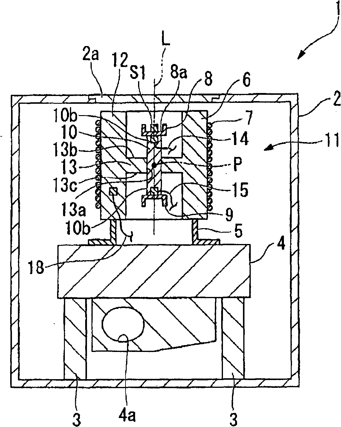
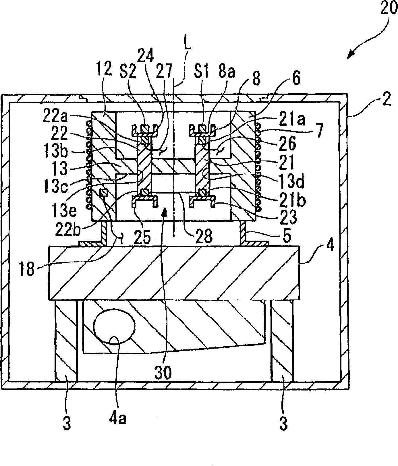
[0036] attached image 3 and 4 A second embodiment of the present invention is shown. In the second embodiment of the present invention, the same elements as those of the first embodiment are denoted by the same reference numerals and explanations thereof will be omitted.

[0037] In the differential scanning calorimeter 20 according to the second embodiment of the present invention, a pair of through holes 13d and 13e are formed at the heat inflow portion 13 of the heat sink 6, and the first thermal resistance member 21 and the second thermal resistance member 22 are respectively fixed at the heat inflow portion 13, and pass through the corresponding through-holes 13d and 13e. The first thermal resistance member 21 and the second thermal resistance member 22 have an approximately rod-like shape with a uniform cross-section, and may be made of a material having lower thermal conductivity than the material of the heat sink 6 . For example, the thermal resistance members 21 a...


PUM


Abstract

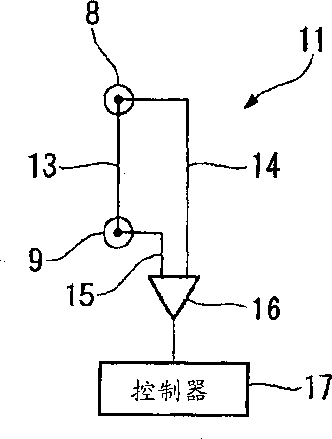
There is provided a differential scanning calorimeter for exactly measuring a calorie variation of the measured sample on the basis of the temperature difference between sample container and the reference container without the influence of the heat irregularity incoming from the surroundings and the noise components. The differential scanning calorimeter includes a heating furnace of an approximately H-shaped section having an approximately drum-shaped wall part and an approximately plate-shaped heat inflow part, a heater disposed outside the wall part so as to heat the heating furnace, a approximately bar-shaped heat-resistance member that is arranged along the center axis L of the wall part, that protrudes from both sides of the heat inflow part by an approximately equal length, that is made of a material heat conductivity lower than that of the material of the heating furnace, a sample container disposed at one end of the heat-resistance member, a reference container disposed at the other end of the heat-resistance member, and a differential heat flow detector measuring a difference between the temperature of the sample container and the temperature of the reference container as a measured value.

Description

technical field [0001] The invention relates to a thermal analysis device for measuring the changing characteristics of a sample according to the temperature change. In particular, the present invention relates to a differential scanning calorimeter for measuring a sample compared to a reference sample based on the temperature difference (differential calorimetry) between the two samples when the temperatures of both the sample and the reference sample are varied. Excess heat emitted or absorbed. Background technique [0002] A differential scanning calorimeter is used to detect differentially the excess heat emitted or absorbed by a sample compared to a reference sample, provided that both samples are thermally stable when the temperature of the sample under test and the reference sample change at a constant rate, such as aluminum side by side set up. More particularly, the differential scanning calorimeter may include a cylindrical furnace having a base plate, a heater f...

Claims


Application Information

Patent Timeline
Patent Type & Authority Applications(China)
IPC IPC(8): G01N25/48
CPCG01N25/20
Inventor 寺本芳彦
Owner HITACHI HIGH TECH SCI CORP
Learn More