Device for controlling an electric protection device and electric protection device including same

A technology of electrical protection and operating devices, which is applied in the direction of emergency protection devices, protection switch operation/release mechanisms, parts of protection switches, etc., can solve the problem that the size of magnetic and thermal protection devices cannot be further reduced, cannot be optimized, and the locking force can be reduced And other issues

Active Publication Date: 2008-10-01
SCHNEIDER ELECTRIC IND SAS
View PDF0 Cites 12 Cited by
  • Summary
  • Abstract
  • Description
  • Claims
  • Application Information

AI Technical Summary

Problems solved by technology

Since the mechanical dimensions are related to the standard dimensions of the molded circuit breaker pole-units, this geometry is not optimal for further reducin...

Method used


Image

  • Device for controlling an electric protection device and electric protection device including same
  • Device for controlling an electric protection device and electric protection device including same
  • Device for controlling an electric protection device and electric protection device including same

Examples


Embodiment Construction

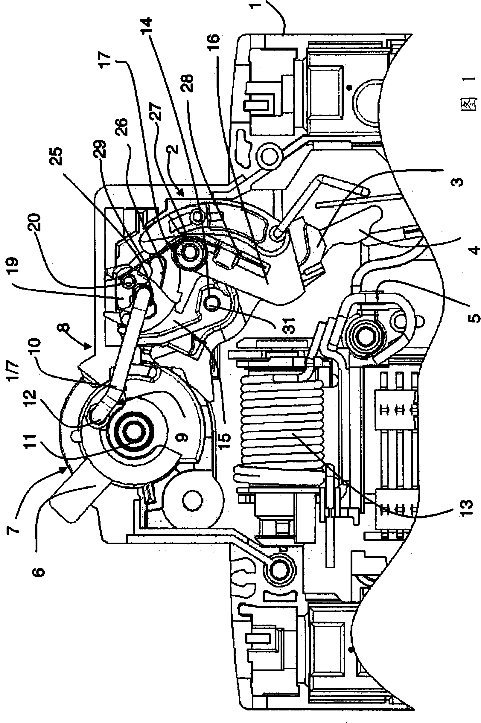
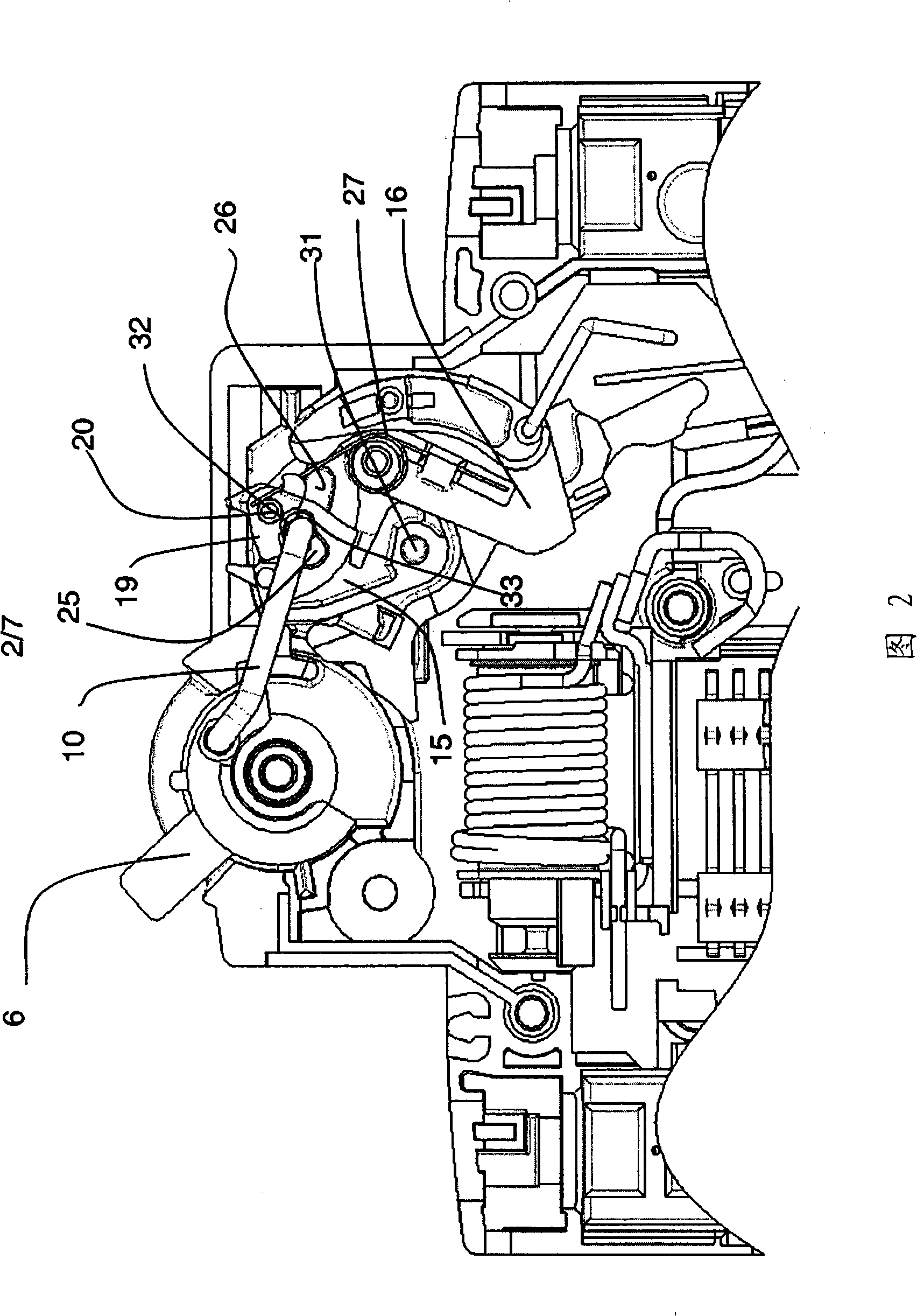
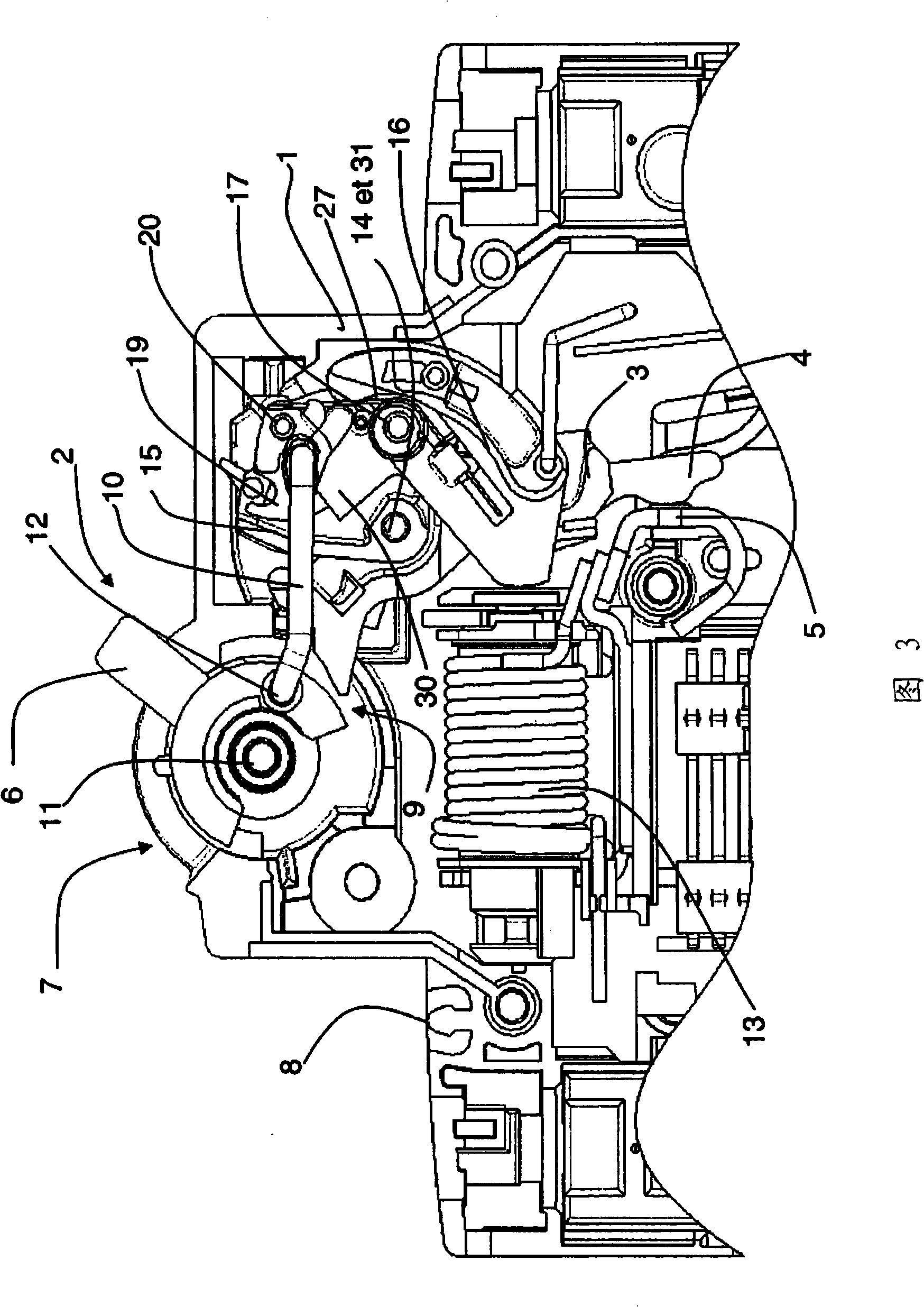
[0023] In these figures, it can be seen that a pocket circuit breaker with a molded insulating housing 1 comprises an operating device 2 according to the invention. The device comprises support means 3 of a movable contact part 4 acting in conjunction with a stationary contact part 5 .

[0024] On the front plate 8 of the housing there is provided an opening 7 serving as a passage for a handle 6 which is mounted so as to be limitedly pivotable on a pin 11 of the housing between the closed position in which the contact parts 4, 5 are in the closed state and between the disconnected positions corresponding to the separation of the contact parts 4,5. The handle 6 is equipped with an internal base 9 joined to a transmission rod 10 to form a toggle arrangement, the joint 12 of which is not concentric with the fixed pin 11 of the handle 6 .

[0025] The handle 6 is biased counterclockwise to the off position of the contact portion by a return spring (not shown). The stationary con...


PUM


Abstract

An operating device of electric protection equipment contained in an insulating shell body containing a pair of static and movable contact parts. The device comprises: a drive link coupled to a handle; a supporting device of the movable contact part including a mounting plate rotatablely installed on a pivot shaft and a machine coupling part separated from the drive link; an unlocking pole controlled by an unlocking device so that the machine can automatically unlock and separate the contact parts no matter the handle is at any state; a separable machine coupling part composed of a remaining notch of the unlocking pole of a pin coupled with a locking element rotatablely installed on the plate; wherein the drive link at the locking position of the locking element is pressed on the plate and the locking element, and the relative position of two supporting surfaces respectively of the plate and the locking element and the proportion of two bar linkages are selected so that the force applied onto the locking element is smaller than that applied onto the plate.

Description

technical field [0001] The invention relates to an operating device for electrical protective equipment housed in an insulating housing comprising a pair of stationary and movable contacts, which can be actuated manually by means of a handle or Automatically drives the movable contact part. Background technique [0002] In the known patent FR 2 589 627 the transmission rod acts in conjunction with the support plate. In this device, the mechanical force acts 2 / 3 on the plate and 1 / 3 on the trip bar. This has no mechanical benefit in terms of reducing the forces involved. [0003] Known patent FR 2 616 583 describes an operating mechanism of a pocket electrical circuit breaker including the features mentioned above. [0004] In this document, an assembly comprising a transmission lever, a lock, and a trip lever forms a reduction gear stage that reduces the tripping force. [0005] In this mechanism, the force of the rod creates a torque on the lock. Since the mechanical d...

Claims


Application Information

Patent Timeline
IPC IPC(8): H01H71/52H01H73/50
CPCH01H71/526
Inventor 伊薇斯·贝林
Owner SCHNEIDER ELECTRIC IND SAS
Why Eureka
Try Eureka