Coupling circuit and network device for power line communication

A technology of power line communication and coupling circuit, which is applied in the field of coupling circuit and can solve problems such as the inability to use PLC communication

Inactive Publication Date: 2008-10-01
YAMAHA CORP
View PDF1 Cites 15 Cited by
  • Summary
  • Abstract
  • Description
  • Claims
  • Application Information

AI Technical Summary

Problems solved by technology

If the coupling circuit described in Patent Document 1 as described above is connected to such wiring, there will be a problem that a high-frequency bypass will occur not only between the lines L1-L2 but also in the lines L1-N Between and between L2-N, which will result in the inability to use PLC for communication in the whole house wiring

Method used


Image

  • Coupling circuit and network device for power line communication
  • Coupling circuit and network device for power line communication
  • Coupling circuit and network device for power line communication

Examples


Embodiment Construction

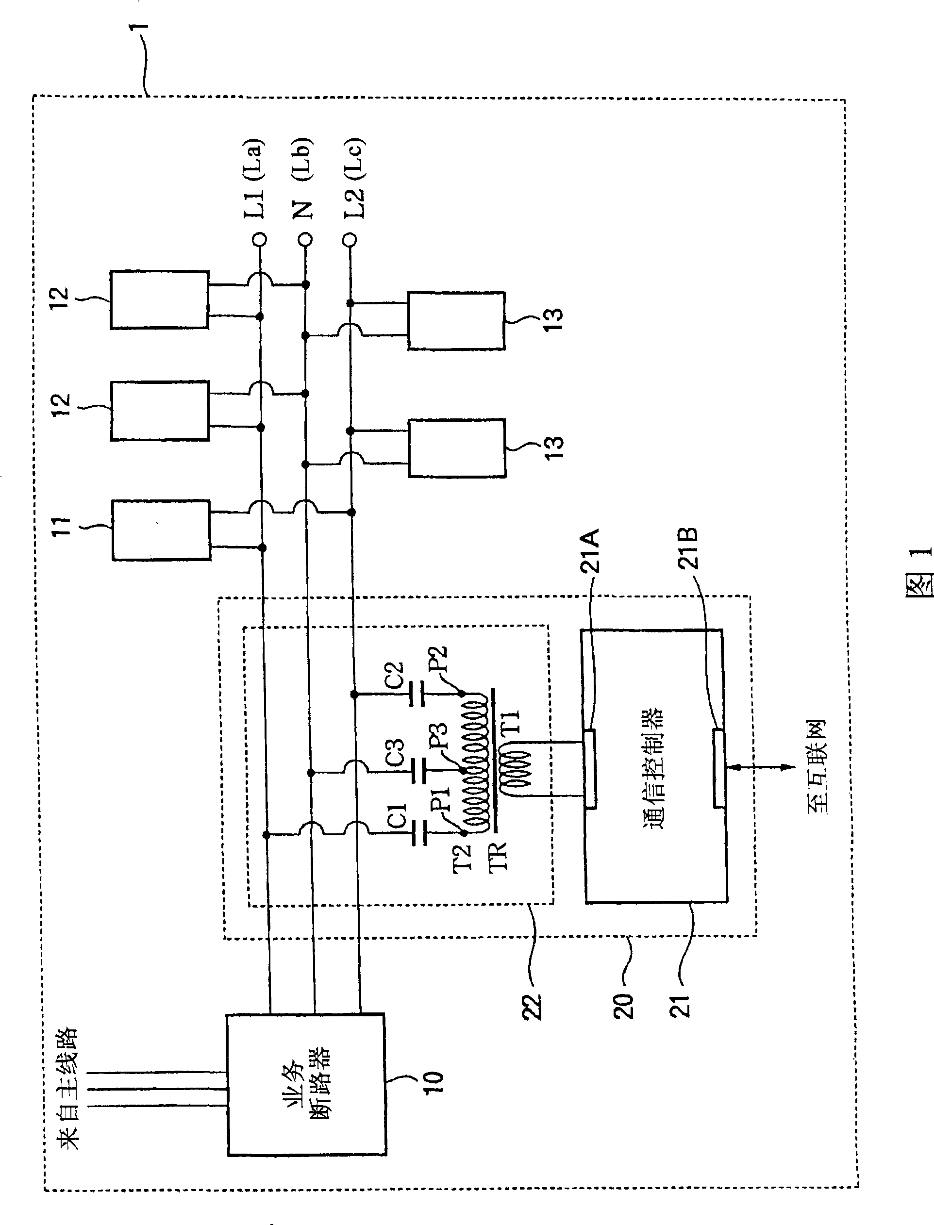
[0022] A network device for PLC according to an embodiment of the present invention will now be described with reference to the accompanying drawings. The PLC network equipment is used to equally connect three pairs of single-phase three-wire indoor power lines connected from the main power line to the WAN Internet.

[0023] FIG. 1 is a view showing the structure of a distribution board incorporating a PLC network device according to a first embodiment of the present invention. The switchboard 1 is connected to a single-phase three-wire electrical mains line, such as a line carried by a pole. The single-phase three-wire type power line is output from the switchboard as power supply lines L1 and L2 and a neutral line N through a three-wire type service circuit breaker (current limiter) 10 . In some cases, the neutral wire can be grounded and used as a ground. These three lines can form three different pairs, and each pair can carry a voltage of 200V or 100V. More specificall...


PUM


Abstract

A coupling circuit is used in a power line communication system for bridging a signal of a high frequency between lines of a single-phase three-line type which feed an electric current having a low frequency as compared to the high frequency of the signal and which include a first power source line, a second power source line and a neutral line. The coupling circuit has a transformer operating at a high frequency and having a primary winding and a secondary winding. The primary winding is provided for connecting with a device having a communication capability of the signal. The secondary winding has a pair of end terminals provided for connections to the first and second power source lines, respectively, and an intermediate tap provided between the pair of the end terminals for a connection to the neutral line. Capacitors having a capacitance effective to pass the signal of the high frequency and effective to cut off the electric current of the low frequency are inserted into the respective connections to the first power source line, the second power source line and the neutral line.

Description

technical field [0001] The present invention relates to a coupling circuit for power line communication (PLC) capable of simplifying power line communication through a distribution board; and to a network device for PLC using the coupling circuit. Background technique [0002] Today, power line communication (PLC) using power lines spread throughout the country is about to be realized for digital communication. PLC is mainly applied to home networks using indoor wiring, not to telecommunication using high-voltage lines (see Non-Patent Document 1). [0003] Recently, a single-phase three-wire system is used in Japan to bring power from the main power line to the home even in domestic applications. Figure 4 An example of a single-phase three-wire type distribution board is shown. Three lines L1 , L2 and N are connected to the distribution board through a service circuit breaker 100 . Each of the three pairs of lines L1-L2, L1-N and L2-N supplies 200V or 100V of power, respe...

Claims


Application Information

Patent Timeline
Patent Type & Authority Applications(China)
IPC IPC(8): H04B3/56
CPCH03H7/0138
Inventor 山崎详平
Owner YAMAHA CORP
Why Eureka
Try Eureka