Condensate drainage with maintenance interface

A technology of condensate and discharge, applied in steam traps, transportation and packaging, machinery and equipment, etc., can solve the problem of time-consuming and expensive replacement of parts

Active Publication Date: 2006-12-27
BEKO TECHNOLOGIES GMBH
View PDF1 Cites 3 Cited by
  • Summary
  • Abstract
  • Description
  • Claims
  • Application Information

AI Technical Summary

Problems solved by technology

The cost mainly depends on whether the replacement of various parts is time-consuming and expensive
Another disadvantage of the above...

Method used


Image

  • Condensate drainage with maintenance interface
  • Condensate drainage with maintenance interface
  • Condensate drainage with maintenance interface

Examples


Embodiment Construction

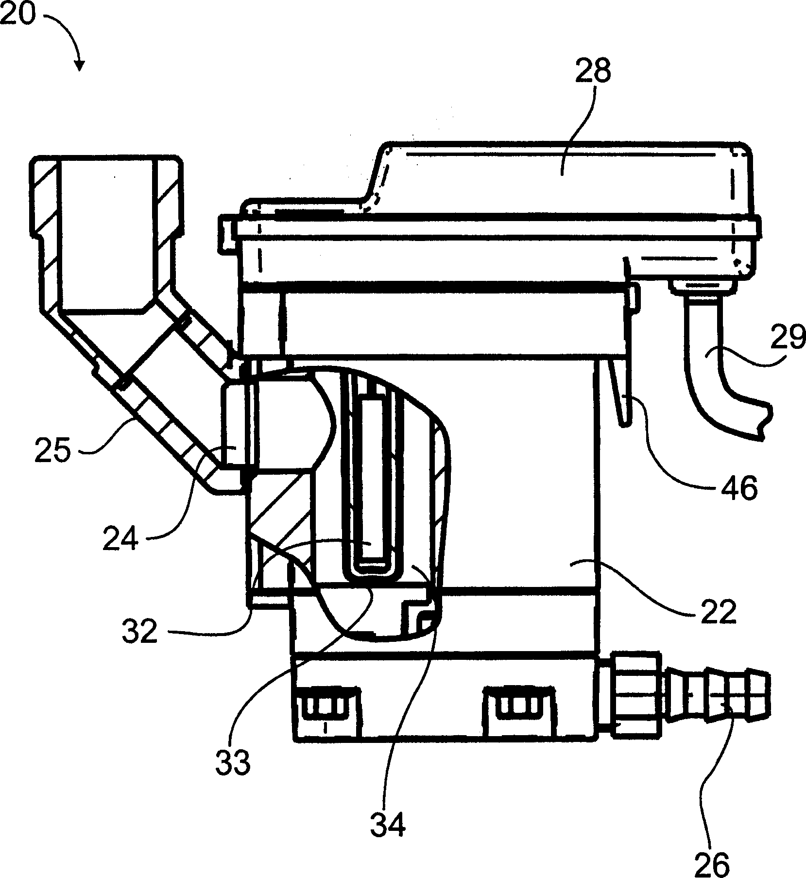
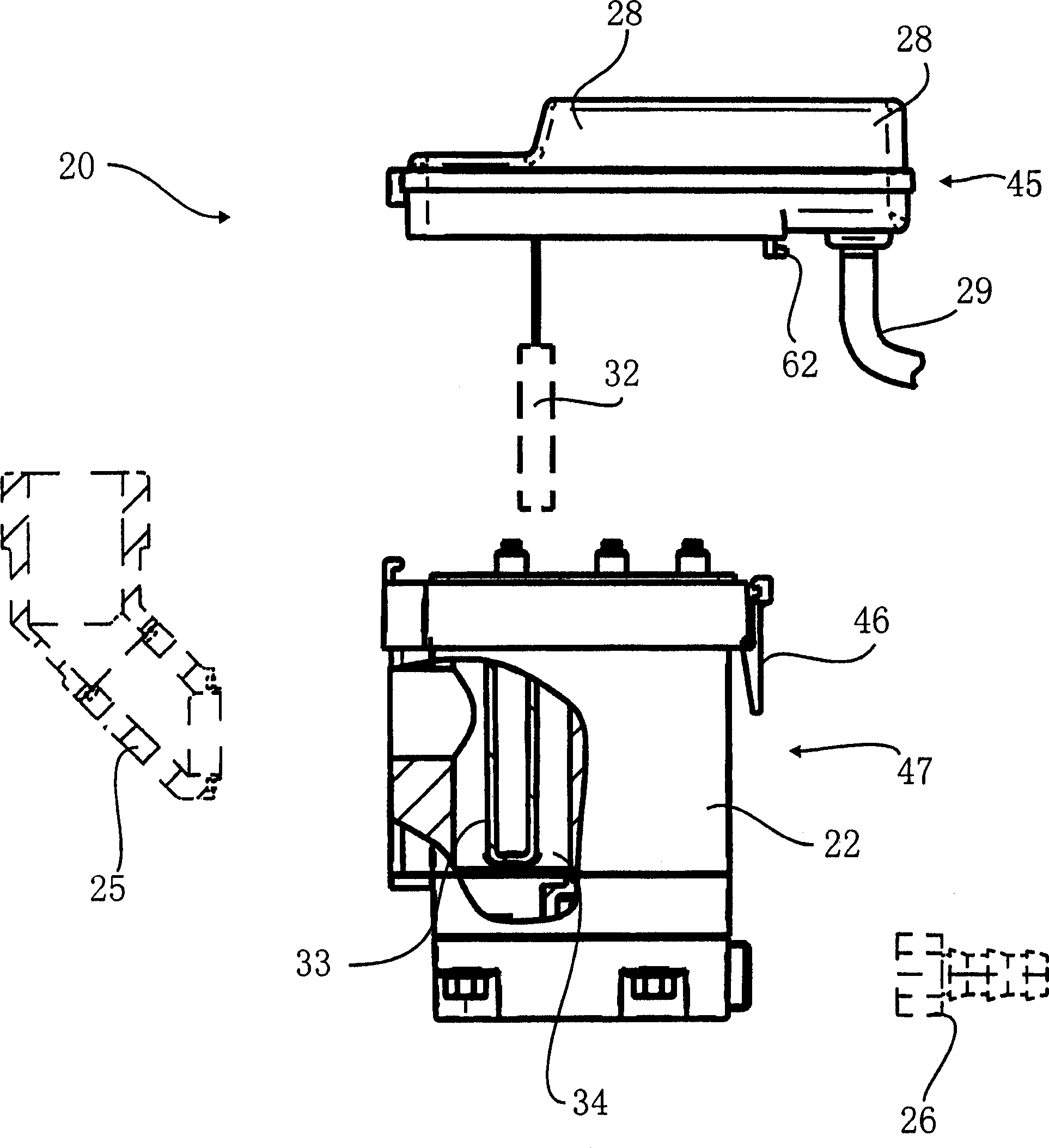
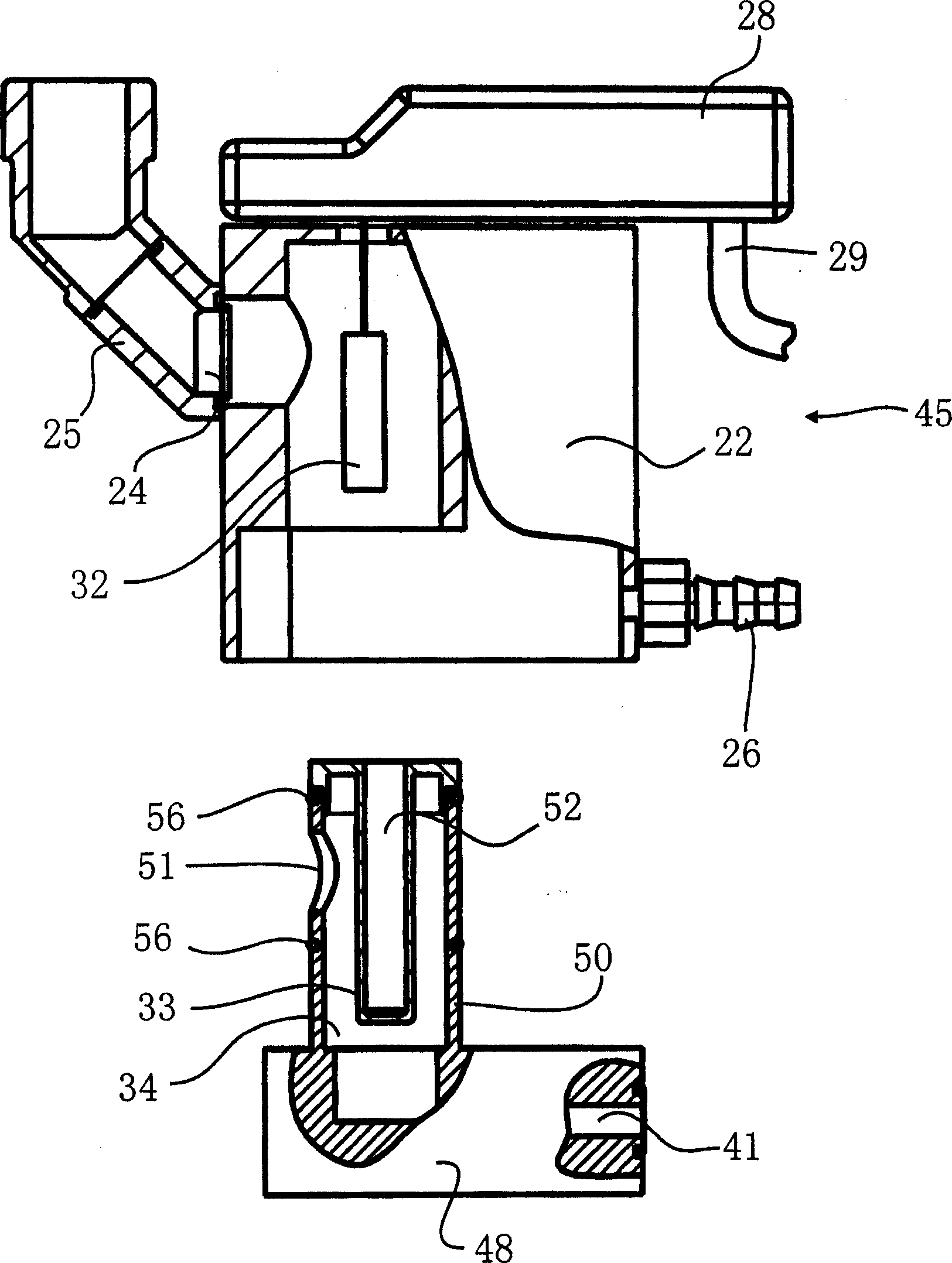
[0026] Each figure shows the air filter water drainer 20 of the present invention. It has a housing 22 with a compressed air connection 24 for connection to a pressurized gas line, in particular a compressed air line 25, and an outlet 26 for discharging condensed water to the outside .

[0027] An electronic unit 28 is connected to the housing 22 . The electronics unit 28 includes a power connection 29 for connection to a power source. Also, the electronics unit 28 is connected to a level indicator 32 which in this embodiment comprises several capacitive sensors. Each of these sensors is connected to the electronic unit 28 by wires. In this way, the condensate level in this container can be recorded by capacitive electronics without any parts subject to wear.

[0028] The level indicator 32 protrudes from above into a collection chamber 34 in which condensed water is deposited and collected via a compressed air connection, which is also connected to the collection chamber ...


PUM


Abstract

A steam trap 20 is used for draining off condensate from a collecting chamber 34 in which condensate resulting in a pressure gas system is collected, the collecting chamber 34 being pressurised by a gas pressure which, depending upon the operating state of the pressure gas system, may be a negative pressure below the atmospheric pressure, an overpressure above the atmospheric pressure or an atmospheric pressure itself. The steam trap 20 may be separated via an interface into an integral first assembly unit 45 and an integral maintenance assembly unit 47 which comprises the essential wear and tear parts.

Description

technical field [0001] The invention relates to a gas filter drainer for discharging condensed water collected in a collection chamber which is generated in a pressurized gas system, the gas pressure in the collection chamber may be Negative pressure lower than atmospheric pressure, positive pressure higher than atmospheric pressure or just atmospheric pressure, this air filter water release device includes the following components: [0002] a. A liquid level indicator designed to indicate the level of condensate collected in the collection chamber, especially when the liquid level in the collection chamber reaches or exceeds a maximum liquid level; [0003] b. an outlet valve, which communicates with the collection chamber and is designed to discharge condensate from the collection chamber, in particular capable of releasing condensate against atmospheric pressure; [0004] c. An electronic unit capable of releasing condensate by opening the outlet valve in response to a sig...

Claims


Application Information

Patent Timeline
IPC IPC(8): F16T1/00
CPCF16T1/12F16T1/16F16T1/48F16T1/38Y10T137/304Y10T137/3068
Inventor J·辛斯特德顿
Owner BEKO TECHNOLOGIES GMBH
Why Eureka
Try Eureka