Method and apparatus for removing jitter in demapping, method and apparatus for obtaining clock, phase discriminator

A demapping and clocking technology, which is applied in the field of optical communication, can solve problems such as the inability to obtain readout clocks, and achieve the effect of filtering jitter and high-performance data output

Inactive Publication Date: 2008-10-01
HUAWEI TECH CO LTD
View PDF0 Cites 7 Cited by
  • Summary
  • Abstract
  • Description
  • Claims
  • Application Information

AI Technical Summary

Problems solved by technology

However, since the read and write clocks on both sides of the demapping unit are all clocks with large gaps, the writing and reading of data are all performed in a read/write manner with large gaps. Therefore, during the creation process of the present invention, The inventors have found that there are at least the following prob

Method used


Image

  • Method and apparatus for removing jitter in demapping, method and apparatus for obtaining clock, phase discriminator
  • Method and apparatus for removing jitter in demapping, method and apparatus for obtaining clock, phase discriminator
  • Method and apparatus for removing jitter in demapping, method and apparatus for obtaining clock, phase discriminator

Examples


Embodiment Construction

[0034] Embodiments of the present invention provide a method and device for dejittering during demapping.

[0035] In order to make the technical solutions of the embodiments of the present invention more clear, the embodiments of the present invention will be further described in detail below with reference to the accompanying drawings and examples.

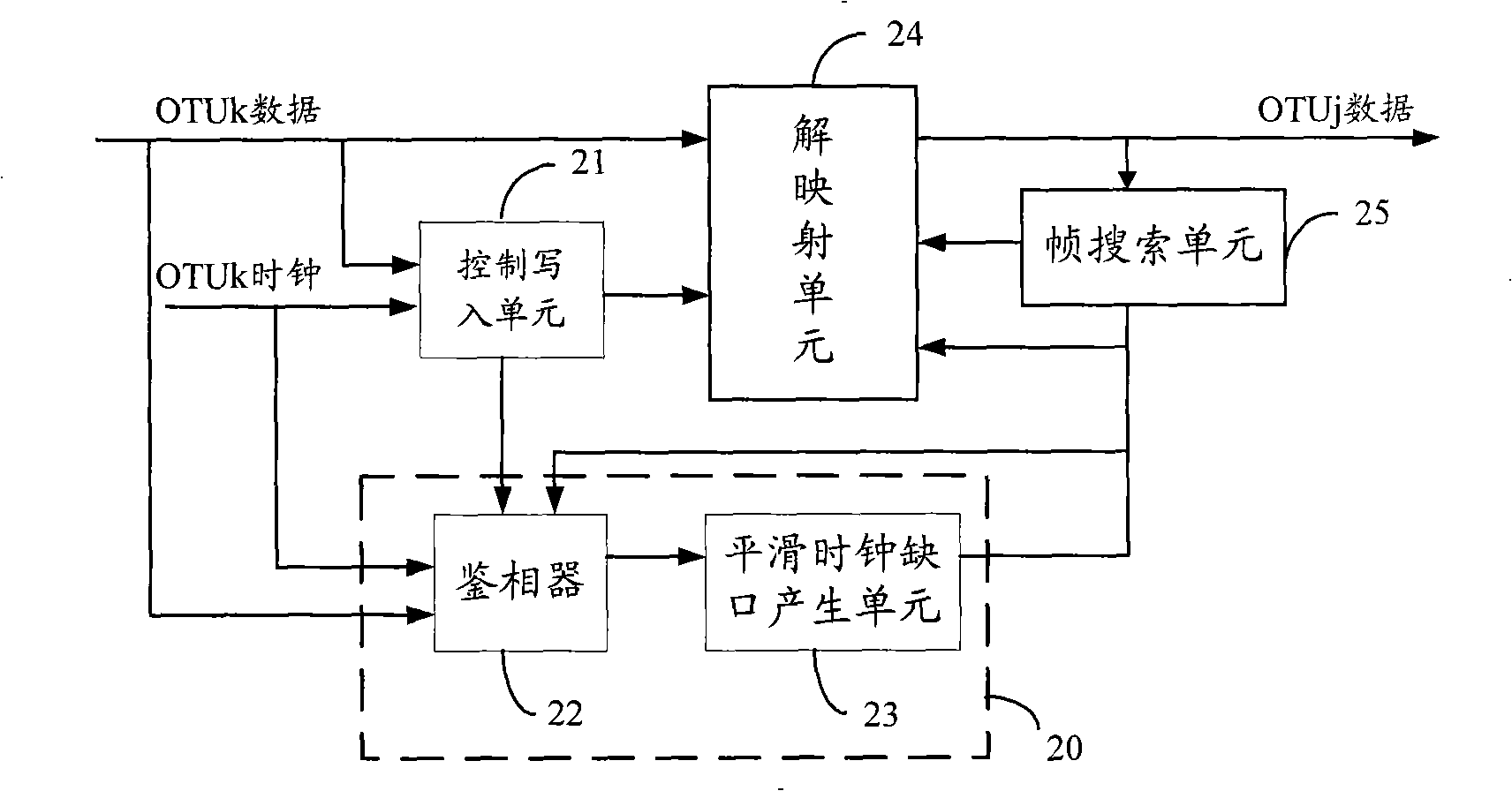
[0036] see figure 2 , is a structural diagram of the first embodiment of the de-jittering device in demapping according to the present invention. In this embodiment, the de-jittering device in demapping is used to demap the input high-rate OTUk data to obtain low-rate OTUj data. The debounce device in demapping includes a control writing unit 21 , a data readout clock acquisition unit 20 , a demapping unit 24 , and a frame search unit 25 .

[0037] The control writing unit 21 is used to demap the mapping structure of the OTUk data, the clock corresponding to the OTUk data, and the adjustment information carried in the OTUk da...


PUM


Abstract

The invention provides a dithering-removal method and device in de-mapping, a clock obtain method and device, and a phase detector. The dithering-removing method in de-mapping includes: data required de-mapping is processed de-mapping and is cached according with data writer clock; data writer virtual clock and data reader precast clock is obtained according with data required de-mapping and corresponding clock; data writer virtual clock and data reader precast clock are compared, data reader clock is generated according with the comparison result; data after being de-mapping is read according with the data reader clock. The technical solution provided by the invention can obtain dithering condition generated in de-mapping course effectively, filter dithering generated in data de-mapping course effectively by adjusting clock in time, and obtain data output with high performance.

Description

technical field [0001] The invention relates to the technical field of optical communication, in particular to a debounce method and device in demapping, a clock acquisition method and device, and a phase detector. Background technique [0002] In the case of the wide application of Optical Transport Network (OTN, Optical Transport Network), there are multiple low-rate Optical Channel Transport Unit (OTU, Optical Channel Transport unit) signals that are multiplexed and mapped into the high-rate OTU network for transmission. Requirements; and high-rate OTU signal demapping to obtain multiple low-rate OTU signals. A large amount of mapping and combining jitter will inevitably be generated during the data demapping process, and OTN services have high requirements on jitter, so it is necessary to filter out the jitter generated during the demapping process to ensure clock performance. [0003] The prior art provides a debounce method in demapping, please refer to figure 1 , is...

Claims


Application Information

Patent Timeline
IPC IPC(8): H04J3/06H04J3/16
Inventor 尹辉
Owner HUAWEI TECH CO LTD
Why Eureka
Try Eureka